


Pelco Manual C543M-A (7/03) 13
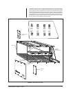
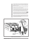
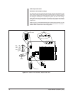
To the right of the Alarm Connector is a Video Black Level Output BNC which can
be used as a reference sync output to allow for genlocking of peripheral devices.
The signal level for this output is 300 mV. The connection for this output is a stan-
dard BNC connector. The output has a 75-ohm termination. The Video Black Level
BNC can be seen in Figure 5.
Below the two connectors just discussed is the RJ-45 connector or data port, which
provides the main RS-422 communication path between the matrix bay and an
appropriate SerCom port on the rear of a CM9760-CC1.
Power supply input terminal plugs, ON/OFF switches, and power supply input fuses
for both power supply positions (whether the power supply is installed or not) are
located at the bottom of the power supply panel. The top set of this twin configura-
tion is for the top power supply; the bottom for the bottom (refer to Figure 5). Further
details of power supply configuration are discussed in Section 2.2.5 and 3.2.
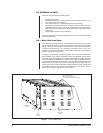
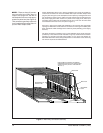
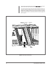
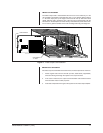
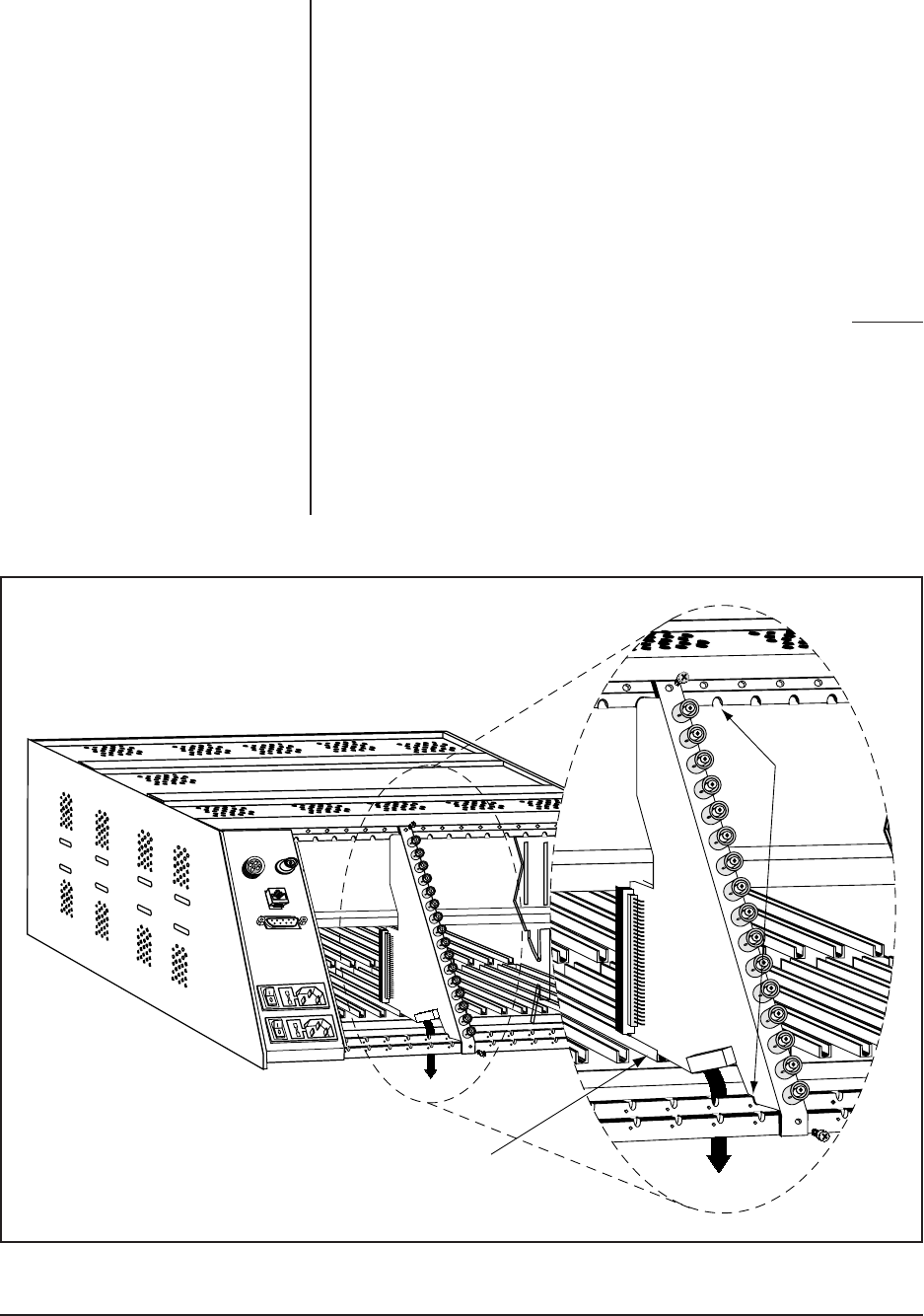
To the right of the power supply bays are the openings for installing the
rear panel
Input and Output cards. These cards provide a video signal path for the Video Input
and Output cards that plug into the matrix bay from the front. These unique, trian-
gular shaped cards are held laterally in place by top and bottom notched rails and
a small rear portion of the guide rail into which the cards fit (refer to Figure 7).
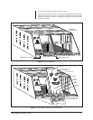
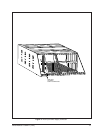
In addition, the cards are snugly secured to the matrix bay frame by screws which
hold the top and bottom of each card’s faceplate to the frame of the matrix bay
(refer to Figure 8). The dual BNC Rear Input card discussed in Section 2.2.4 is held
in place with four screws, two at top and two at bottom. Unused rear openings are
covered by appropriately sized blank plates.
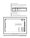
Figure 7. Matrix Bay and Rear Input Cards
NOTCHED
RAILS
INTO
WHICH
CARDS
FIT
DOWNFRAMING
PATH
REAR INPUT CARDS
SLIDE PARTIALLY INTO
BACK PORTION OF
CARD GUIDE