


18 Pelco Manual C543M-A (7/03)
Other Important Items
DIP Switch and Jumper Settings
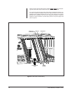
The matrix bay has a DIP switch (S2) and jumpers (JP2 and X55) located on the
Video Output Card that enable the selection of different options. These are normally
set in the proper position upon leaving the factory. However, it is recommended that
the settings be checked prior to operating the system (the other “front loading”
Video Input Cards have no DIP switches or jumpers to verify). Refer to the following
paragraphs for a complete description of the switches and jumpers on the Video
Output Card.
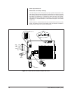
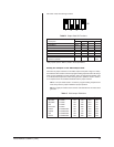
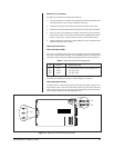
Refer to Figure 12. Switch S2 determines the communications baud rate, how the
system will operate on power up and whether video loss detection is enabled or
disabled. Refer to Table B for S2 switch assignments.
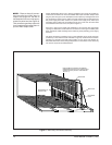
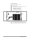
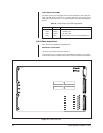
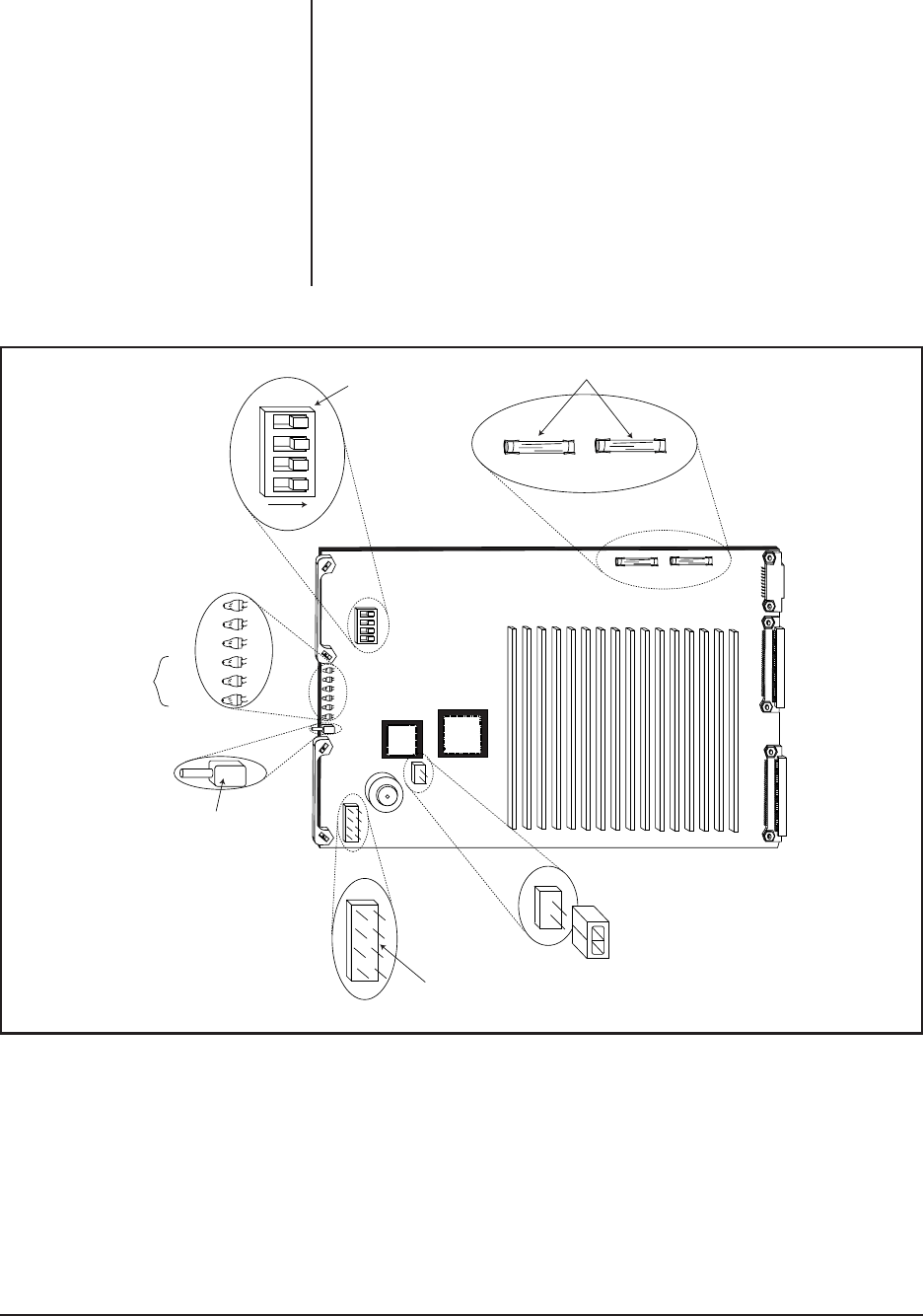
Figure 12. Location of DIP Switches, Jumpers and Fuses
RESET
SWITCH
X55
(SEE TABLE C)
RED DS6
GREEN DS5
GREEN DS4
DS3
AMBER DS2
DS1
JP2
F6
F7
FUSES, BOTH .7ASB
S2
(SEE TABLE B)
1
23
4
ON