


Pelco Manual C543M-A (7/03) 35
3.4 LED DIAGNOSTICS
Each component installed in the matrix bay is equipped with diagnostic LEDs (most
of which have already been mentioned) to aid in system troubleshooting. All LED
assignments are repeated below (for convenience) in Table G.
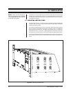
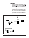
3.4.1 Performing a Diagnostic LED Check
Prior to connecting any video input or output to the matrix bay, it is recommended
that you first power up the unit to ensure the system is operating properly. Refer to
the following checklist to ensure the matrix bay is operating correctly at this time.
1. Apply power to the unit.
2. Ensure both power LEDs on the supply (or supplies) are illuminated.
3. Ensure both the Frame Fault and the Supply Fault LEDs are OFF.
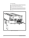
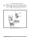
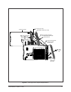
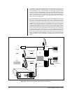
4. Remove the front panel and check the power LEDs on each of the Video
Input/Output Cards. Both LEDs should be illuminated. If any board has a prob-
lem, remove the board(s) and inspect the fuses. Replace fuse (if necessary)
and reinstall into the frame. If the condition continues, replace the defective
board with a known good board.
5. Ensure all Comm Fail LEDs are OFF. If this LED is ON on any Input card,
reseat the board. If the condition continues, replace with a known good board.
If all the Comm Fail LEDs are illuminated, press the reset button located on
the Output card. If the problem continues, replace with a known good board. If
the LED is illuminated on the Output Card only, check the communications to
the CM9750 Controller.
6. If everything is OK, install all video inputs and outputs as described in para-
graph 3.5.
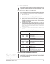
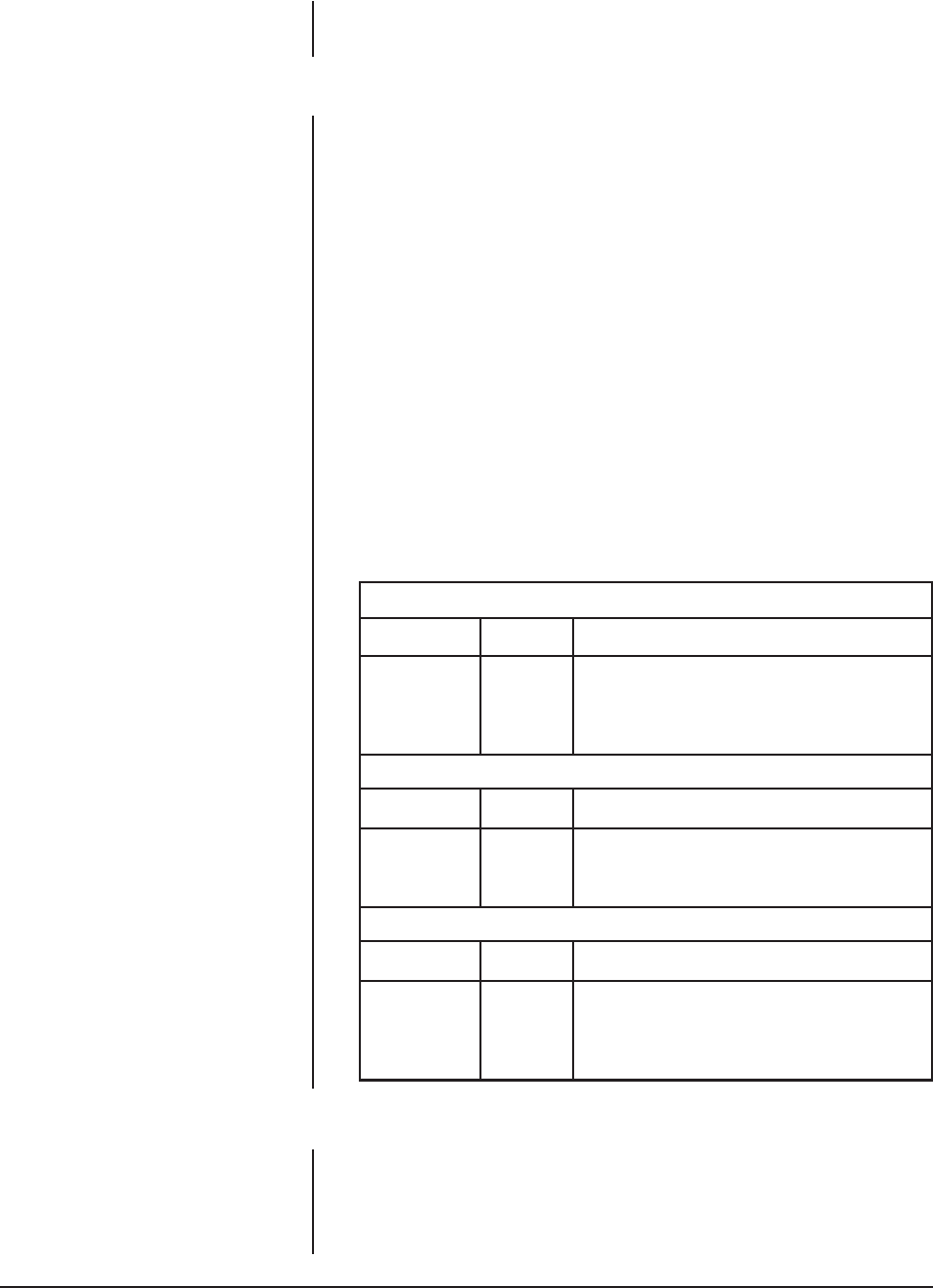
Table G. Matrix Bay LED Assignments
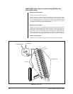
Video Output Card LEDs
LED COLOR WHEN LED IS ON
DS1 to DS3 Amber Always ON, No assignment
DS4 Green –10 VDC is OK
DS5 Green +10 VDC is OK
DS6 Red Communications failure with the CM9760-CC1
Video Input Card LEDs
LED COLOR WHEN LED IS ON
CR1 Red Communications failure with the CM9760-CC1
CR2 Green +10 VDC is OK
CR3 Green –10 VDC is OK
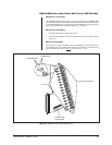
Power Supply Module LEDs
LED COLOR WHEN LED IS ON
+10 V Green Normal Operation
–10 V Green Normal Operation
Frame Fault Red (flashing) Failure of one or more cards
Supply Fault Red Failure of associated power supply
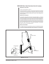
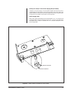
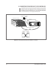
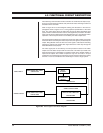
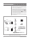
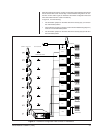
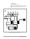
3.5 CONNECTING VIDEO INPUTS/OUTPUTS
All video inputs and monitor outputs are connected to the Rear Panel BNC Cards.
Be sure each connection is secure and that the connectors are installed properly.
When connecting the inputs and outputs to the rear panels, allow enough slack in
the cable to act as a strain relief.
NOTE:
When wiring inputs it is
always good installation practice to
label each video input. This can save
a considerable amount of time should
troubleshooting be required.