


Pelco Manual C543M-A (7/03) 3
LIST OF ILLUSTRATIONS
Figure Page
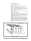
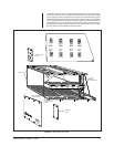
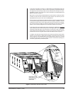
1 Front of Matrix Bay ............................................................................8
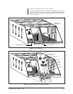
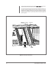
2 Matrix Bay Card Cage .......................................................................9
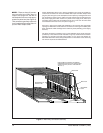
3 Matrix Bay Connection Geometry .....................................................10
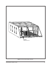
4 Rear of Matrix Bay ............................................................................ 11
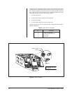
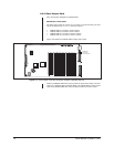
5 Power Supply Section of Rear Matrix Bay ........................................11
6 Alarm Connector ...............................................................................12
7 Matrix Bay and Rear Input Cards .....................................................13
8 Rear Input Card Mounting ................................................................14
9 Rear Input Power Supply Connector ................................................15
10 Video Output Card with 16 Monitor Outputs (CM9760-VMC16) .......16
11 Video Output Card Installation ..........................................................17
12 Location of DIP Switches, Jumpers and Fuses ................................18
13 Video Input Card ...............................................................................20
14 Video Input Card Installation.............................................................22
15 Input Card LED and Fusing Locations ..............................................23
16 CM9760-RPC Rear Panel BNC Input Card ......................................24
17 Installation of RPC Input Card ..........................................................25
18 DFC Card ..........................................................................................27
19 RPL Card ..........................................................................................28
20 CM9760-RPM Video Output Card ....................................................29
21 Power Supply Installation .................................................................30
22 Jumper Position on Bottom of Power Supply ...................................31
23 Mounting the Matrix Bay ...................................................................32
24 Replacing Power Supply Fuses ........................................................33
25 Connecting the Matrix Bay to the CM9760-CC1 Controller ..............34
26 Video Signal Flow–Block Diagram ....................................................36
27 Video Signal Flow–Graphical Representation ..................................37
28 System Configuration–Reference Conventions ................................38
29 Single Bay Configuration–256 Cameras x 16 Monitors ....................39
30 Single Bay Downframe–256 Cameras x 32 Monitors .......................40
31 Downframe Configuration–256 Cameras x 128 Monitors .................41
32 Single Sideframing–496 Cameras x 16 Monitors .............................42
33 Sideframe Configuration–976 Cameras x 16 Monitors .....................43
34 Sideframe/Downframe Configuration–496 Cameras x
32 Monitors .......................................................................................44
35 Sideframe/Downframe Configuration–976 Cameras x
128 Monitors .....................................................................................45
36 Sideframe/Downframe Configuration–2048 Cameras x
128 Monitors .....................................................................................46
37 Setup File Dialog Box with Comms Tab Opened ..............................48
38 Configuration File Dialog Box ...........................................................48
39 Camera Files and Logical Numbers .................................................50
40 Physical and Logical Numbers Compared........................................51
41 Physical/Logical Numbers, Sideframed Bays and Camera Files ......52
LIST OF TABLES
Table Page
A Alarm Port Pin Definition...................................................................12
B Output Card S2 Functions ................................................................19
C X55 Jumper Definitions .....................................................................19
DVideo Output Card LED Assignments ...............................................20
E Physical Input Range per Slot Position.............................................21
FVideo Input Card LED Assignments..................................................23
G Matrix Bay LED Assignments ...........................................................35