


Pelco Manual C543M-A (7/03) 27
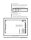
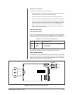
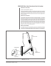
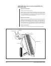
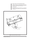
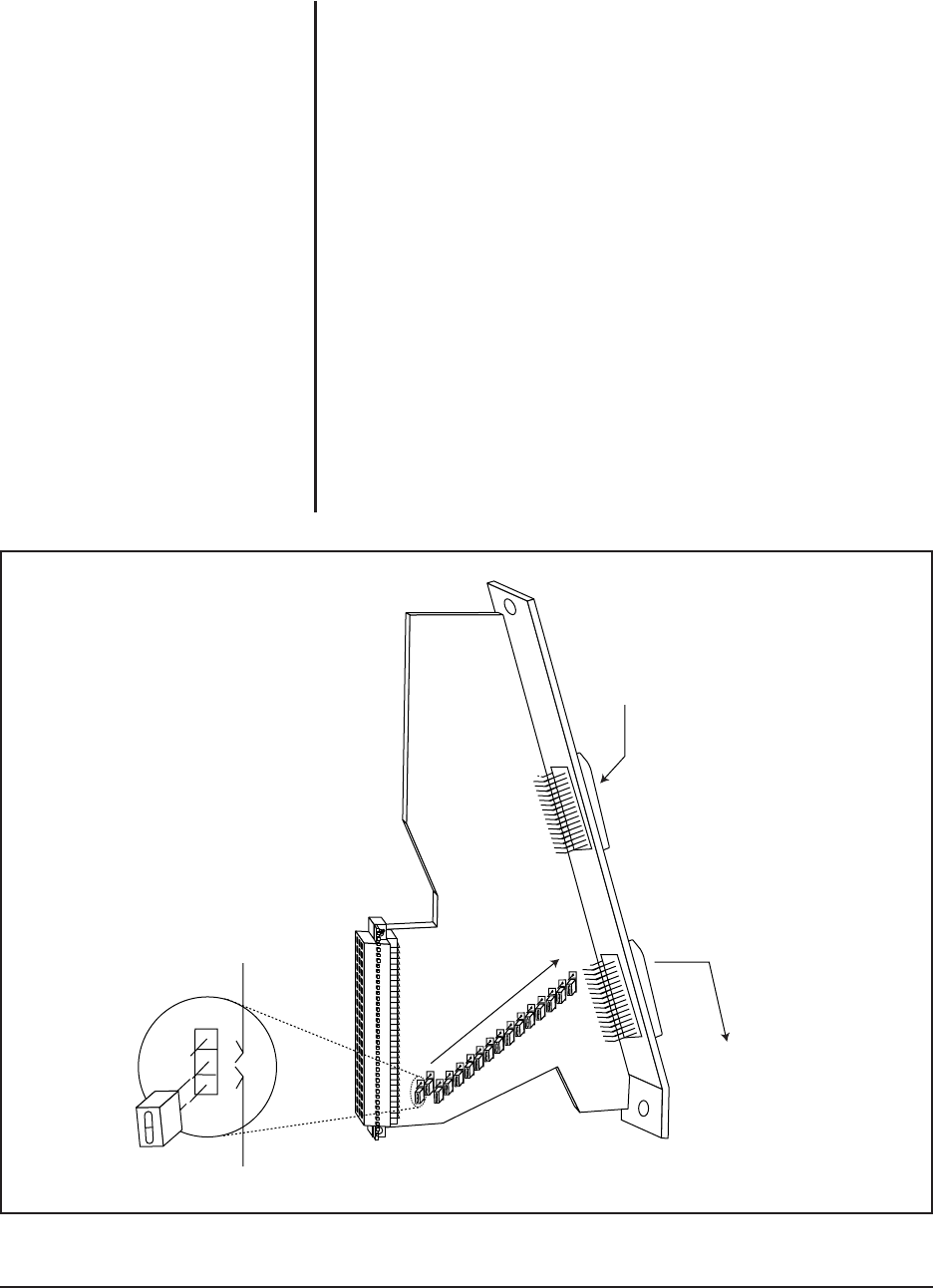
Figure 18. DFC Card
JP
1
JP
16
OUTPUT
TO BAY BELOW
INPUT
FROM BAY ABOVE
UNTERMINATED
TERMINATED
3
2
1
CM9760-DFC (Rear Panel Downframe Card, No Looping)
What Does It Look Like?
The DFC card is illustrated in Figure 18.
Note that instead of BNC connectors on the spine of the card there are two identical
16-pin male connectors. Note that there are termination jumpers on the board. Also
note that there is no connector located on the bottom area of the board as was the
case for previously illustrated rear panel cards. The DFC card is supplied with a
downframing cable.
What Are Its Functions?
The downframe card’s almost sole function is as its name implies — to provide a
signal path for the addition of more monitors in extended framing situations while at
the same time aiding full cross-point functionality of the downframed configuration.
For every bay between the first and last, a DFC card is used to interconnect the
associated intermediate bays. The DFC card can also be used in the last bay in a
downframe configuration. Note that when the DFC card is used in the intermediate
bays, the termination jumpers must be set in the unterminated position. When the
DFC card is used in the last bay in a downframe configuration, the termination
jumpers must be set in the terminated position.
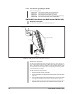
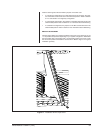
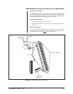
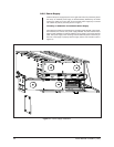
Where Is It Installed?
It is installed in any of the 16 slot positions of any bay in a downframing configura-
tion where it is needed. It is physically installed in the same manner as any other
rear panel card. For additional information, refer to Section 5.1 on downframing.