


36 Pelco Manual C543M-A (7/03)
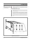
4.0 FUNCTIONAL CIRCUIT DESCRIPTION
The matrix bay communicates with the Controller via an RS-422, full-duplex, asyn-
chronous communications interface and performs all video switching functions as
directed from the Controller.
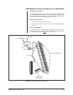
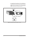
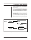
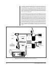
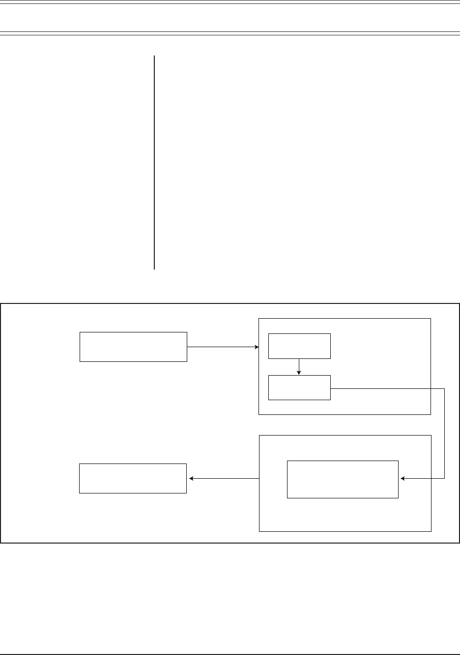
Refer to Figure 26 for a block diagram outlining the discussion in the next few
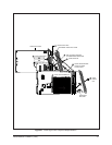
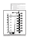
paragraphs. Refer to Figure 27 for a more graphical representation of the same
thing. The video signal enters the matrix bay through the Rear Panel BNC Card
(Input) where it is terminated with 75 ohms. The signal then proceeds to the Video
Input Card via the input buffers and is then directed to the 16 x 16 crosspoint switch.
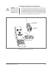
Operation of the crosspoint switch is controlled by the Video Output Card.
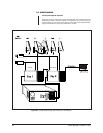
The signal leaves the Video Input Card and is sent to the Video Output Card via the
video bus. When received by the Video Output Card, the signal is processed by the
Output Titling Module where the DC level of the signal is restored and the titling
message is inserted. The edited video signal leaves the matrix bay through the
Rear Panel BNC Card (Output).
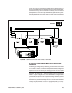
The video signal path is controlled by the microprocessor located on the Video
Output Card. The Video Output Card has full control of all Video Input Cards. The
basic functional group is essentially a crosspoint switch with a variable number of
inputs and 16 outputs. The number of inputs can vary from 16 to 256, in 16 input
increments. The functional group (matrix bay) can be used as a stand alone routing
switcher or it can be connected to other matrix bays to create a larger system.
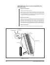
Figure 26. Video Signal Flow–Block Diagram
VIDEO INPUT
VIDEO OUTPUT
REAR PANEL BNC CARD
CM9760-RPC
REAR PANEL BNC CARD
CM9760-RPM
VIDEO INPUT CARD
VIDEO OUTPUT CARD
INPUT
BUFFER
16 X 16
CROSSPOINT
SWITCH
CM9760-VCC
VIDEO OUTPUT MODULE
CM9760-VMM
CM9760-VMC