


10 Pelco Manual C543M-A (7/03)
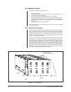
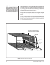
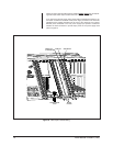
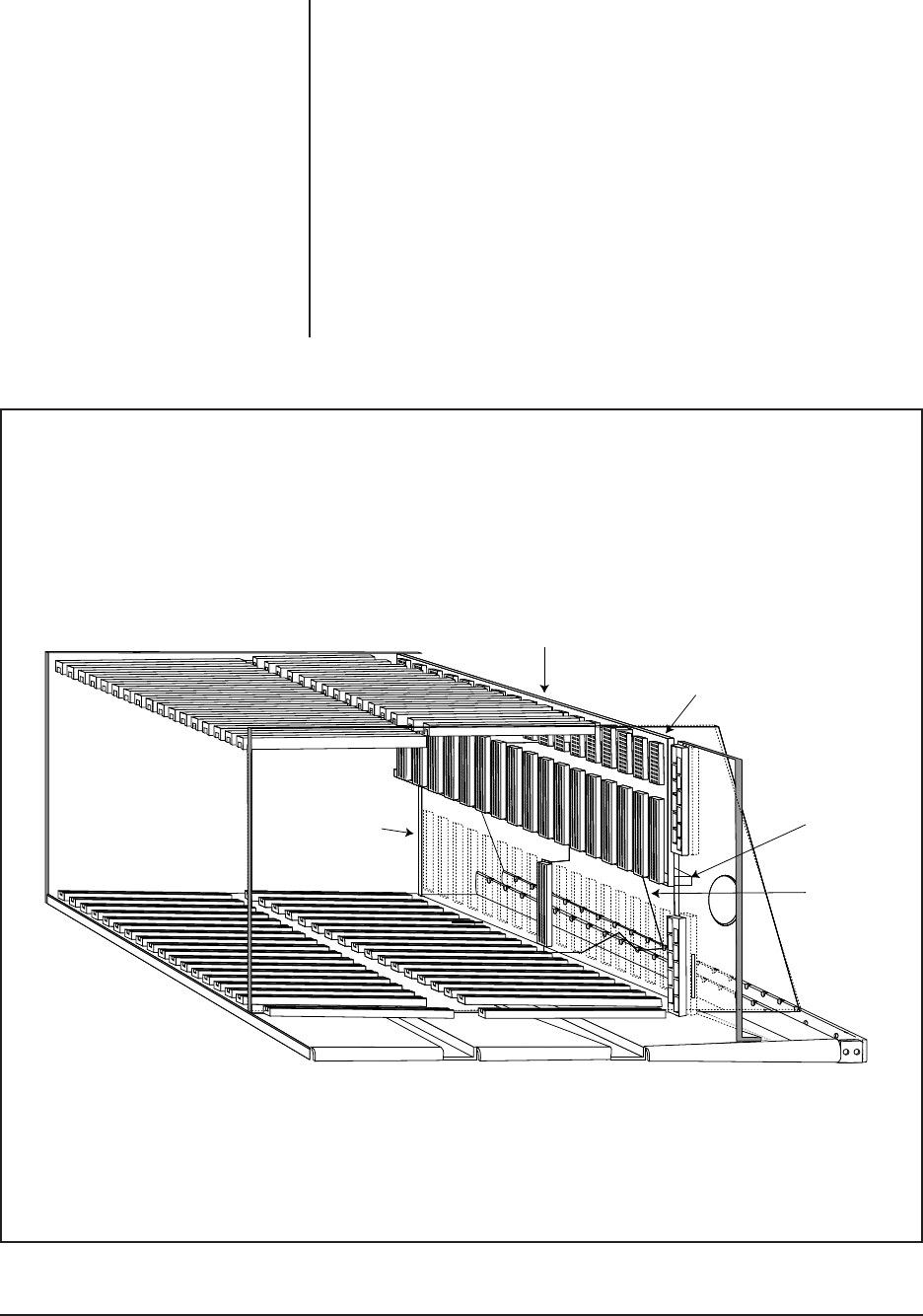
Further disassembly allows one to see the backplane upon which are located two
of the three connectors into which all installed Video Input and Video Output cards
plug into (refer to Figure 3). The back plane is held in place by rectangular bar stock
(top and bottom) which runs the width of the bay between the left side panel and
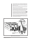
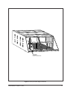
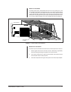
the power supply plate which secures it in place. Power supply units, Video Input
and Video Output Cards are all installed from the front of the unit. All other cards
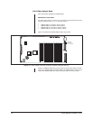
are installed from the rear of the unit (refer to Figure 4).
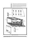
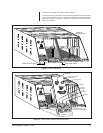
Also note in Figure 3 the baffle plate installed for CE purposes with appropriate
openings for Rear Panel cards and their connectors to fit through. The baffle plate
itself, extends the width and height of the matrix bay itself (excluding power supply
sections).
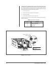
The three connectors (consisting of two on the backplane and a single connector
provided by a Rear Panel card as indicated in Figure 3) constitute the connection
geometry for all Video Input and Output Cards. For any given card position an
associated Rear Panel card (card type dependent on the function of the matrix bay
into which it fits) must be installed FIRST.
Figure 3. Matrix Bay Connection Geometry
REPRESENTS CE
BAFFLE PLATE
NOTE EXAMPLE OF VERTICAL ALIGNMENT
ORIENTATION INTO WHICH ALL VIDEO/OUTPUT
CARDS PLUG INTO (OUTPUT CARD SPECIFIC
TO SLOT 17)
BACKPLANE
BAR STOCK
REAR PANEL
CARD
NOTE:
There are three (3) connec-
tors into which any Video Input or
Output Card plugs into: the two on
the backplane and one on the appro-
priate rear panel card (see Figure 3).
This connection geometry holds true
for all installed front loaded Video In-
put and Video Output cards.