


38 Pelco Manual C543M-A (7/03)
5.0 SYSTEM CONFIGURATION–FRAMING
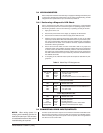
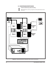
When either more cameras and/or more monitors are needed than can be accom-
modated by one matrix bay (256 x 16), then one must resort to either downframing
(to increase the number of monitors available for OUTPUT) or to sideframing (to
increase the number of camera INPUTS available).
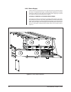
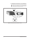
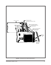
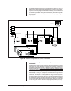
In order to accommodate these larger systems, additional matrix bays will need to
be installed and it is important to note that this requires that the physical location of
additional matrix bays be within the same rack if you are increasing
Output capa-
bilities, since the expansion requires that the bays be hooked together in a vertical
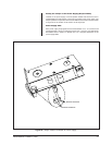
manner or “downframed”. For downframed configurations, leave 1 RU (1.75 inches)
of space between each matrix bay. Similarly, adding
Inputs requires that additional
matrix bays be located in nearby bays since the expansion occurs in a horizontal
manner called “sideframing”. We shall discuss each configuration separately and
follow that with a discussion of more complicated configurations which involve using
both framing methods in a multi-bay configuration.
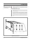
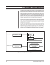
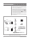
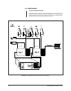
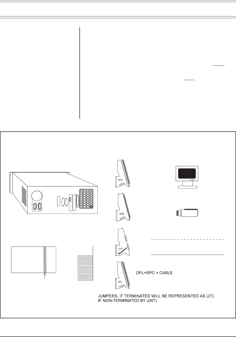
Most of the symbolic references and conventions we shall use in our discussion of
system configurations is represented in Figure 28. Items not listed will be labeled
within the illustration itself.
Figure 28. System Configuration–Reference Conventions
CM9760-CC1
CONTROL OR DATA CABLE
VIDEO CABLE
MATRIX BAY
SLOT 17
VIDEO OUT/RPM CARD
CARD TYPES
MONITOR
CAMERA