


–93–
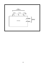
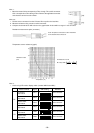
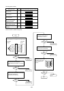
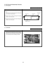
Touch the probes of the tester or other instrument
to the shaded areas to measure.
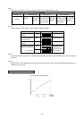
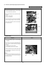
Thermistor Ro=15 kΩ
Rt=15exp 3460 ( – )
1
ON
2345678910
1
ON
2345678910
1
ON
2345678910
1
ON
2345678910
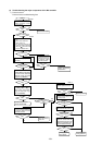
Note 1 :
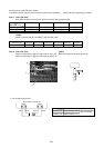
• Board connector CN10 corresponds to TH11 through TH14, while connector
CN11 corresponds to TH15 through TS15. Remove the applicable connector
and check the sensor for each number.
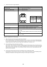
Note 2, 3 :
1. Pull the sensor connector from the I/O board. Do not pull on the lead wire.
2. Measure resistance using a tester or other instrument.
3. Compare measured values with values on the graph below. A value within a range of ±10% is normal.
Resistance measurement point (connector)
Temperature sensor resistance (graph)
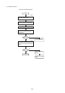
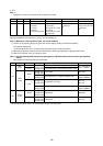
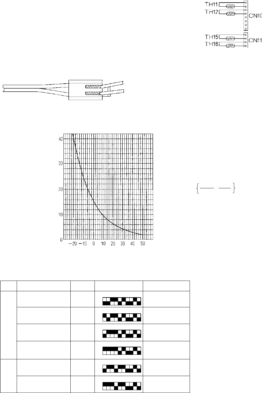
Note 4 :
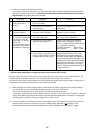
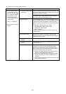
• Check using LED monitor display switch (outdoor MAIN board SW1)
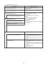
Measured Data Signal SW1 Setting Remarks
Liquid inlet
temperature
Bypass inlet
temperature
Bypass outlet
temperature
Bypass inlet
temperature
Bypass inlet
temperature
Bypass outlet
temperature
TH11
TH12
TH15
TH16
TH22
TH25
See converter.
See converter.
See converter.
See converter.
See converter.
See converter.
FA
FB
1
ON
2345678910
1
ON
2345678910
1
273+t
1
273+0
Resistance value
(kΩ)
Temperature (˚C)