


–45–
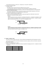
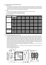
TH9
Four-way valve
Compressor
Accumulator
CS circuit
Separate compressor
TH2
LPS
Heat exchanger
Outdoor heat exchanger
Indoor heat
exchanger
Flow control
valve
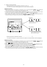
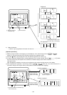
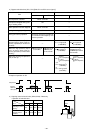
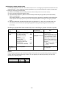
Operation mode
Full cooling
Cooling mainly
Full heating
Heating mainly
Defrosting
ON
ON
OFF
OFF
OFF
OFF
ON
ON
OFF
OFF
OFF
OFF
OFF
ON
ON
ON
ON
OFF
ON
ON
ON
ON
ON
OFF
OFF
ON
ON
ON
ON
OFF
OFF
OFF
ON
ON
ON
ON
OFF
ON
ON
ON
ON
OFF
ON
OFF
ON
ON
ON
OFF
ON
OFF
OFF
ON
ON
ON
ON
OFF
ON
OFF
OFF
OFF
OFF
OFF
OFF
OFF
OFF
OFF
OFF
OFF
OFF
ON
OFF
OFF
OFF
ON
ON
OFF
ON
OFF
OFF
OFF
OFF
OFF
ON
OFF
OFF
OFF
OFF
OFF
OFF
ON
ON
OFF
OFF
OFF
ON
ON
OFF
OFF
OFF
OFF
OFF
ON
OFF
OFF
OFF
OFF
OFF
OFF
ON
ON
OFF
OFF
OFF
ON
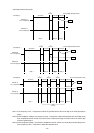
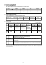
Operation pattern
SV3 SV4 SV5 SV6 SV7 SV8
Solenoid valve
* In stop, all are OFF.
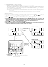
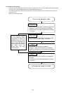
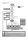
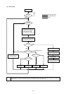
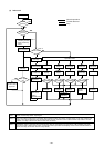
(9) Outdoor unit heat exchanger capacity control
1) Control method
• In order to stabilize the evaporation temperature during cooling and the high-pressure pressure during heating that
are required in response to performance needs, the capacity of the outdoor heat exchanger is controlled by regulat-
ing the fan volume of the outdoor unit by phase control and controlling the number of fans and by using the solenoid
valves to vary the number of out door heat exchangers being used.
2) Control
• When both of the compressors are stopped, the fans for the outdoor units are also stopped.
• The fans operate at full speed for 5 seconds after starting.
• The fans for the outdoor unit are stopped during defrosting.
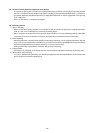
3) Capacity control pattern
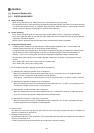
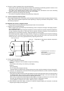
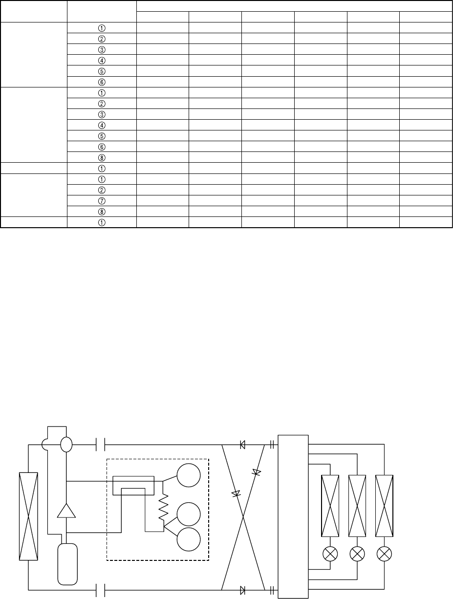
(10) Circulating composition sensor (CS circuit)
• As shown in the drawing below; the CS circuit has the structure to bypass part of the gas discharged from the compres-
sor through the capillary tube to the suction side of the compressor, exchange heat before and after the capillary tube,
and produce two phase (gaseous and liquid) refrigerant at the capillary tube outlet. The dryness fraction of refrigerant at
the capillary tube outlet is estimated from the temperature of high pressure liquid refrigerant at the capillary tube inlet
(TH9) and the temperature of low pressure two phase (gaseous and liquid) refrigerant at the capillary outlet (TH2) and
the pressure (LPS) to calculate the composition of refrigerant circulating the refrigeration cycle (αOC). It is found by
utilizing the characteristic that the temperature of two phase (gaseous and liquid) R407C under a specified pressure
changes according to the composition and dryness fraction (gas-liquid ratio in weight).
• The condensing temperature (Tc) and the evaporating temperature (Te) are calculated from αOC, high pressure
(HPS), and low pressure (LPS).
• The compressor frequency, the outdoor fan, and others are controlled according to the codensing temperature (Tc)
and the evaporating temperature (Te).
• CS circuit configuration (Outline drawing)