


–116–
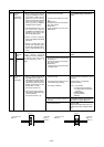
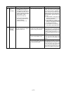
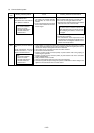
Checking code Meaning, detecting method Cause Checking method & Countermeasure
5201
5201
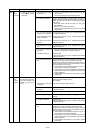
5203
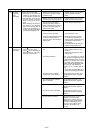
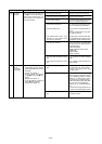
5301
Pressure
sensor
abnormality
(outdoor unit)
IAC sensor/
circuit
abnormality
Pressure sensor abnormality (BC controller)
High
pressure
side
Intermedi-
ate
1
When pressue sensor detects
1kg/cm
2
G (0.098MPa) or less dur-
ing operation, outdoor unit once
stops with 3 minutes restarting
mode, and restarts if the detected
pressure of pressure sensor ex-
ceeds 1kg/cm
2
G (0.098MPa)
imediately before restarting.
2 If the detected pressure of sen-
sor is less than 1kg/cm
2
G
(0.098MPa)
immediately before
restarting, error stop is com-
menced displaying 5201.
3 Under 3 minutes restarting
mode, LED displays intermittent
fault check.
4 During 3 minutes after com-
pressor start, defrosting and 3
minutes after defrosting opera-
tions, trouble detection is ig-
nored.
When high or intermidiate pressure
sensor detects 1kg/cm
2
G
(0.098MPa) or less immediately be-
fore starting, error stop is com-
menced displaying “5201”, or
“5203”.
1 If IAC 3 Arms is detected just
before the inverter starts, or
If IAC 3 Arms is detected dur-
ing inverter operation after 5
seconds has passed since the
inverter started when the INV
board’s SW1-1 is OFF.
[Inverter error detail : 6]
2 If the current sensor (ACCT)
miss-wiring is detected during
inverter operation.
[Inverter error detail : 13]
1) Pressutre sensor trouble.
2) Inner pressure drop due to a leak-
age.
3) Broken cover.
4) Coming off of pin at connector por-
tion, poor contact.
5) Broken wire.
6) Faulty thermistor input circuit of
MAIN board.
1) Pressure sensor trouble.
2) Inner pressure drop due to gas leak.
3) Broken cover.
4) Coming off of pin at connector por-
tion, poor contact.
5) Broken wire.
6) Faulty pressure sensor input circuit
of control board.
1) Contact is faulty.
2) The current sensor (ACCT) is con-
nected with wrong polarity.
3) The wiring is defective
4) The Ac current sensor (ACCT) is
defective.
5) The IPM is defective.
See Troubleshooting of pressure
sensor.
See troubleshooting of pressure
sensor.
Check the contacts of CNACCT on the
INV board.
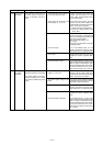
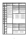
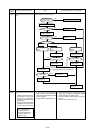
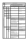
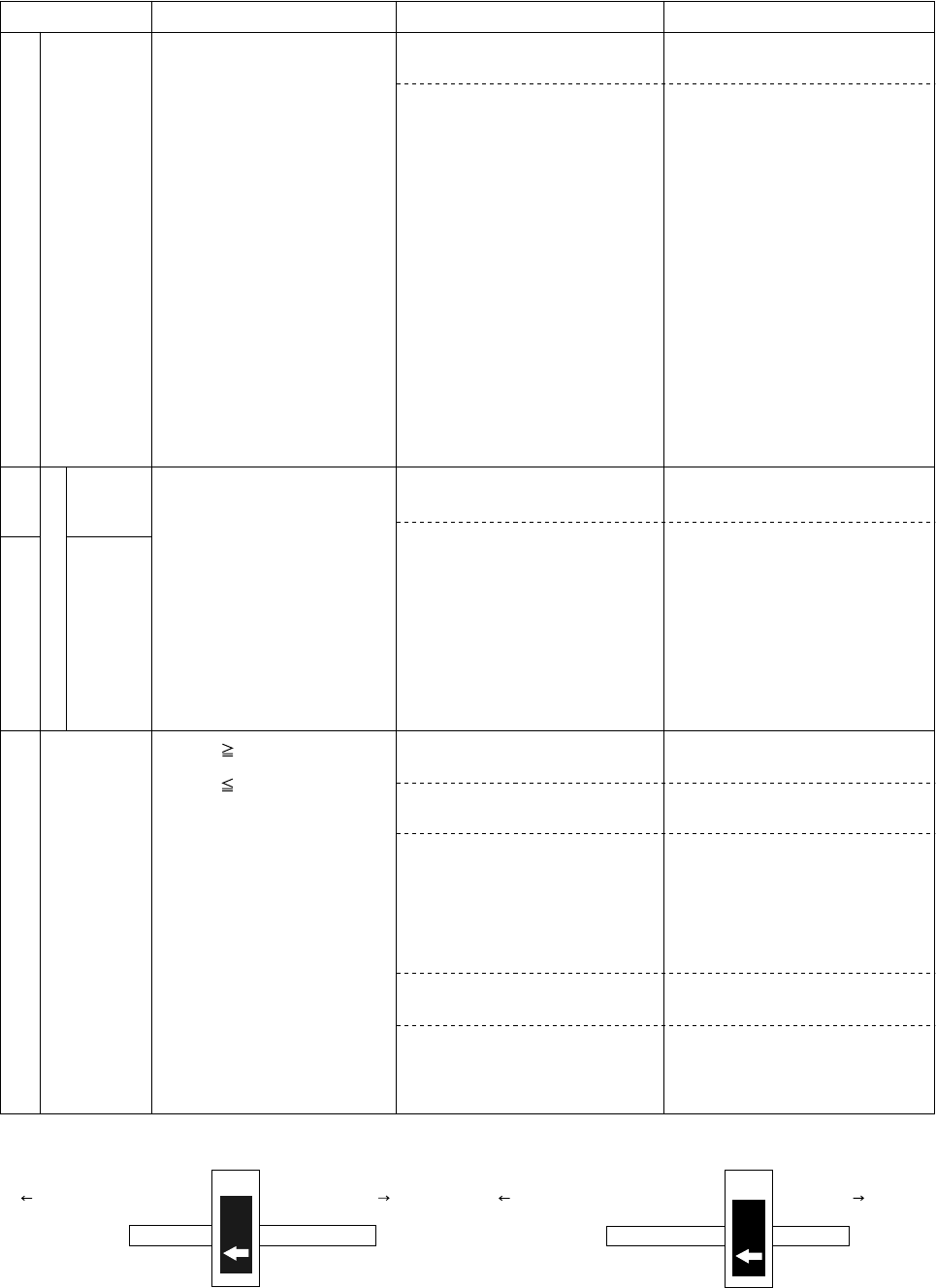
Check the ACCT_U, W polarity
with below drawing.
Check 1. connections.
2. contact at the connectors.
3. for broken wires in the follow-
ing wiring.
CNDR2-CNDR1
CN15V2-CN15V1
IPM-MC1
To judgefailure of ACCT, go to “individual
Parts Failure Judgment Methods.”
Check the IPM.
Judge that the IPM is fauly, (Go to “In-
dividual Parts Failure Judgment Meth-
ods.”)
ACCT_U
U
ACCT_W
IPM-output
phase U
IPM-output
phase W
Compressor-input
phase U
Compressor-input
phase W
Red wire
Black wire
W