


–67–
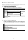
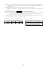
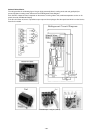
Solenoid Valve (SV1~8)
Check if the control board’s output signals and the operation of the solenoid valves match.
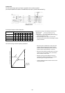
Setting the self-diagnosis switch (SW1) as shown in the figure below causes the ON signal of each relay to be output to
the LED’s.
Each LED shows whether the relays for the following parts are ON or OFF. When a LED lights up, it indicates that the
relay is ON.
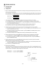
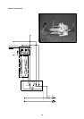
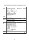
SW1
LED
12345678910
ON
12345678910
ON
SV6aSV4a
SV22/32
SV1
2154a
2154b
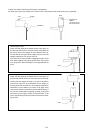
1) SV1 (Bypass valve)
1 Since SV1 will be set to ON 4 minutes after the compressor has started operation, confirm operation by monitoring the
LED display and listening for the operation of the solenoid valve.
2 It is possible to confirm the switching being performed by the operation of the solenoid valve while the unit is operating
by monitoring the temperature of the bypass circuit or the sound of the refrigerant.
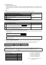
2) SV22, SV32 (Full load/unload switching valve) (only P500YMF-C)
1 The No. 1 compressor is started first and operates for approximately 10 minutes and then the No. 2 compressor starts
in the unload mode. Since it will then switch to full load within 5 minutes, the operation can be confirmed by the LED
display and the operating temperature of the solenoid valve. (If the indoor unit operating is small, the No. 2 compressor
will not start.)
2 It is possible to determine whether or not the compressors are switching from unload to full load by check the changes
in amperage of the compressor at the moment of switching. The amperage under full load will be approximately 30 to
40 % more than operation under unload.
Note: The solenoid valve for SV22 is closed when conducting electricity while the SV32 is open when conducting
electricity.
3) SV4a (Bypass valve)
1 During unload operation in the cooling mode and when there is a rise in temperature and during unload operation in the
heating mode, SV4a will be set to ON according to conditions, making is possible to check operation by the LED
display and the operating sound of the solenoid valve.
2 It is possible to confirm the switching for the operating status by the temperature of the bypass circuit or the sound of
the refrigerant during the operation of the solenoid valve.
4) SV6b
When No. 2 compressor is operating and No. 2 compressor is stopped, the main SV6 will be set to ON, making it
possible to confirm operation by monitoring the LED display and listening to the operating sound. Note that it may be
set to OFF if the outlet temperature (TH11) exceeds 120°C .
5) 21S4a, 21S4b
21S4a, 21S4b are turned on during heating mode and heating-main mode.
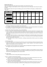
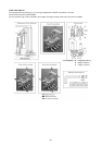
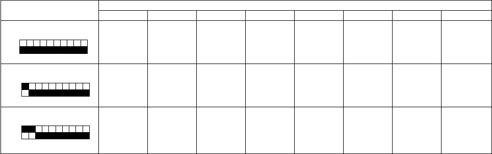
6) SV3 ~ 8 (Control of heat exchanger capacity)
(a) Operations can be confirmed by LED display and operating sound of solenoid valve, because one or more of
SV3 ~8 are turned on depending on conditions during cooling-only operations.
(b) Operation can be confirmed by LED display and operating sound of solenoid valve, because all of SV3 ~ 8 are
turned on during heating-only operations.
(c) Operations can be confirmed by LED display and operating sound of solenoid valve, because one or more of
SV3 ~8 are turned on depending on conditions during cooling-principal and heating-principal operations.
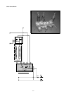
12345678
12345678910
ON
SV3 SV4 SV5 SV6 SV7, 8