


–24–
27.0/19 27.0/19
35.0/24.0 35.0/24.0
55
55
55
55 55
27.1 29.2
27.6/26.2/25.2 34.6/32.8/31.7
2000 300 2000 350
200 344
100 100 100 50 50 125 125 125 100 25
10 10 10 10 10 10 10 10 10 10
Hi Hi Hi Hi Hi Hi Hi Hi Hi Hi
360 360 360 340 340 410 410 410 360 280
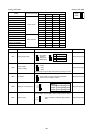
Discharge (TH11/TH12)
Heat exchanger outlet (TH5)
Inlet
Accumulator
Outlet
Suction (Comp) (No.1/No.2)
Low pressure saturation
temperature (TH2)
Upper (TH4)
Liquid level
Lower (TH3)
Shell bottom (Comp No.1/No.2)
CS circuit (TH9)
Circulating configuration (αOC)
LEV inlet
Heat exchanger outlet
DB/WB
Set
-
m
-
kg
A
V
Pulse
Outdoor
unit
Indoor
unit
Outdoor unit
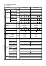
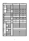
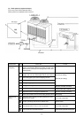
Items
Ambient temp.
Indoor unit
Piping
Condition
Indoor
Outdoor
Quantity
Quantity in operation
Model
Main pipe
Branch pipe
Total piping length
Outdoor unit
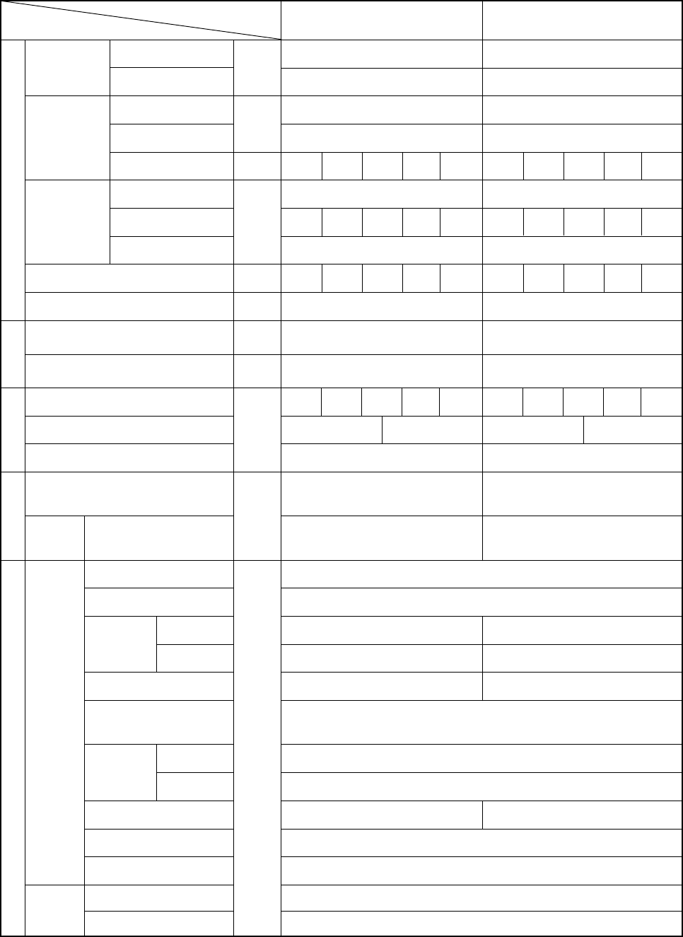
Sectional temperature
Pressure
LEV opening
Indoor unit fan notch
Refrigerant volume
Total current
Voltage
Indoor unit
BC controller (1, 3)
Oil return (SLEV)
380/400/415 380/400/415
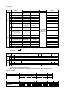
PURY-P400YMF-C PURY-P500YMF-C
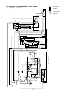
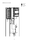
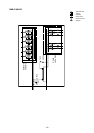
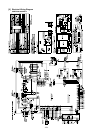
[4] Standard Operation Data
1 Cooling operation
High pressure/Low pressure
(after O/S) (before MA)
kg/cm
2
G
(MPa)
°C
92/102 97/102
42
45
67
6/12 12/12
1
30
1
60/51 65/50
16
0.23
26
12
21.5/4.4 21.5/4.3
(2.11/0.43) (2.11/0.42)
20.5/20.5 20.5/20.5
(2.01/2.01) (2.01/2.01)
BC
controller
High/Intermediate