


–88–
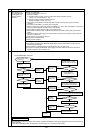
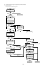
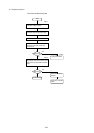
7) Individual Parts Failure Judgment Methods.
Part Name Judgment Method
Diode Stack (DS) Refer to “Judging Diode Stack Failure.”
Intelligent Power Module(IPM) Refer to “Judging IPM Failure.”
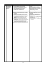
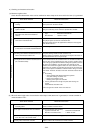
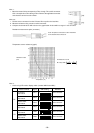
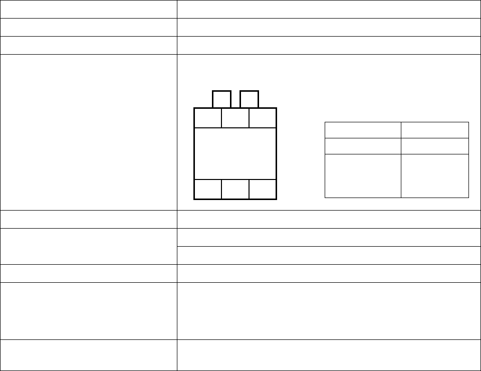
Electromagnetic Contactor (52C) Measure the resistance value at each terminal.
Rush Current Protection Resistor (R1, 5) Measure the resistance between terminals: 4.5k~5.5kΩ
DC Reactor (DCL) Measure the resistance between terminals: 1 Ω or lower
Measure the resistance between the terminals and the chassis: ∞
Cooling Fan (MF1) Measure the resistance between terminals: 0.1k~1.5kΩ
Transformer (T01) Measure the resistance between terminals on the primary side (CNTR1):
1.0k~2.5kΩ
Measure the resistance between terminals on the secondary side (CNTR):
20~60Ω
AC Current sensor (ACCT) Measure the resistance between terminal between 1pin and 2pin, 3pin and
4pin : 35 ~ 45 (Ω)
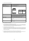
A1A2
1/L1 3/L2 5/L3
2/T1 4/T2 6/T3
Check Location Judgment Value
A1-A2 0.1k~1.3kΩ
1/L1-2/T1
3/L2-4/T2 ∞
5/L3-6/T3
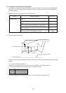
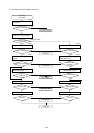
[Caution at replacement of inverter parts]
1 IPM and G/A board should be replaced together at the same time.
When the IPM is damaged, the G/A board may possibly be broken, and the use of the broken G/A board damages
the normal IPM. Therefore, replace the IPM and G/A board together at the same time. However, if the G/A board is
damaged, judge that the IPM is faulty, then judge whether replacement is necessary or not.
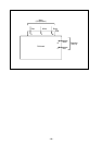
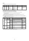
2 Fully check wiring for loose and incorrect connections.
The incorrect or loose connection of the power circuit part wiring like IPM and diode module causes damage to the
IPM. Therefore, check the wiring fully. As the insufficient tightening of screws is difficult to find, tighten them together
additionally after finishing other works. For the wiring of the base for IPM, observe the wiring diagram below care-
fully as it has many terminals.
3 Coat the grease provided uniformly onto the heat radiation surface of IPM /diode modules.
Coat the grease on the full surface in a thin layer, and fix the module securely with the screw for fastening. As the
radiation grease attached on the wiring terminal causes poor contact, wipe it off if attached.