


–110–
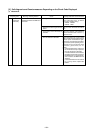
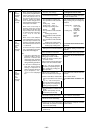
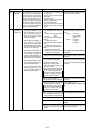
Checking code Meaning, detecting method Cause Checking method & Countermeasure
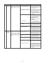
1505
Judging that the state when the
suction pressure reaches 0kg/
cm
2
G (0MPa) during compressor
operation indicates high pressure
by the discharge temperature and
low pressure saturation tempera-
ture, the back-up control by gas
bypassing will be conducted.
• Operation while neglecting to open
ball valve. Especially for the ball
valve at low pressure side.
At cooling : Gas side ball valve
At heating : Liquid side ball valve
• When plural systems are existing,
the low pressure abruptly drop at
indoor stopping by the erroneous
wiring of transmission line (differ-
ent connection of transmission line
and refrigerant piping).
• Temporary vacuum condition due
to refrigerant distribution unbalance
(insufficient refrigerant of low pres-
sure line) immediately after charg-
ing refrigerant.
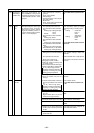
Once vacuum operation protection is
commenced, do not attempt to
restart until taking the measures
below.
<Checking method>
• Check ball valve for neglecting to
open.
• Check extended piping for
clogging when ball valve is
opened.
• Check transmission line for errone-
ous wiring. (Confirm the correct wir-
ing and piping connection between
indoor and outdoor units by oper-
ating indoor unit one by one.)
<Countermeasure>
• After checking with the above
method, make error reset by
power source reset.
• Then operate for 10~15-minutes
under the operation mode reverse
to that when the vacuum opera-
tion protection occurred (Heating
if error occurred in cooling, while
cooling if it occurred in heating),
and then enter into the ordinary
operation state.
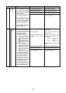
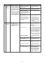
When drain sensor detects flood-
ing during drain pump OFF.
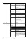
When indirect heater of drain sen-
sor is turned on, rise in tempera-
ture is 20 deg. or less (in water) for
40 seconds, compared with the
temperature detected before turn-
ing on the indirect heater.
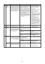
Short/open is detected during drain
pump operations. (Not detected
when drain pump is not operating.)
Short : 90˚C or more detected
Open : -40˚C or less detected
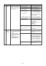
When float switch operates (point
of contact : OFF), error stop is ob-
served with code No. “2503” dis-
played.
1) Water leak due to humidifier or the
like in trouble.
1) Drain sensor sinks in water be-
cause drain water level rises due
to drain water lifting-up mechanism
trouble.
2) Broken wire of indirect heater of
drain sensor.
3) Detecting circuit (circuit board)
trouble.
1) Thermistor trouble.
2) Poor contact of connector.
(insufficient insertion)
3) Full-broken of half-broken ther-
mistor wire.
4) Indoor unit circuit board (detecting
circuit) trouble.
1) Drain up input trouble.
2) Poor contact of float switch circuit.
3) Float switch trouble.
Check water leaking of humidifier
and clogging of drain pan.
Check operations of drain pump.
Measure resistance of indirect heater
of drain sensor.
(Normal: Approx. 82Ω between 1-3 of
CN50)
Indoor board trouble if no other
problems is detected.
Check resistance of thermistor.
0˚C : 15kΩ 10˚C : 9.7kΩ
20˚C : 6.4kΩ 30˚C : 4.3kΩ
Check contact of connector.
Indoor port trouble if no other
problem is detected.
Check drain pump operations.
Check connect contact.
Check float switch operations.
Suction
pressure
abnormality
Leakage (water)
abnormality
Drain pump
abnormality
Drain sensor
abnormality
Operation of
float switch
2500
2502
2503