


–115–
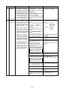
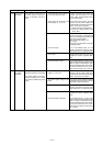
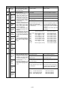
Checking code Meaning, detecting method Cause Checking method & Countermeasure
4260
5101
5102
5103
5104
5105
5106
5107
Cooling fan
abnormality
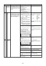
Thermal sensor abnormality (BC controlled)
If the heat sink temperature (THHS)
100°C for 20 minutes or longer just
before the inverter starts.
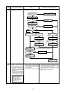
<Other than THHS>
1 A short in the thermistor or an
open circuit was sensed. The
outdoor unit switches to the
temporary stop mode with re-
starting after 3 minutes, then if
the temperature detected by the
thermistor just before restarting
is in the normal range, restart-
ing takes place.
2 If a short or open circuit in the
thermistor is detected just be-
fore restarting, error code
“5101”, “5102”, “5103”, “5104”,
“5105”, “5106”, “5108”, “5109”
or “5112” is displayed.
3 In the 3 minute restart mode,
the abnormal stop delay LED is
displayed.
4 The above short or open circuit
is not detected for 10 minutes
after the compressor starts, or
for 3 minutes during defrosting
or after recovery following de-
frosting.
<THHS>
If a heat sink (THHS) temperature
of -40°C is detected just after the
inverter starts or during inverter
operation.
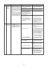
Discharge
(TH11, TH12)
Low
pressure
saturation
(TH2)
Liquid level
detection
(TH3)
Liquid level
detection
(TH4)
Heat
exchanger
inlet pipe
(TH5)
Ambient
tempera-
ture (TH6)
Heat
exchanger
outlet pipe
(TH7)
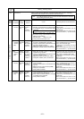
Thermal sensor abnormality (Outdoor Unit)
Same as “4230.”
Check the thermistor’s resistance.
Check if the lead wires are pinched.
Check for tearing of the insulation.
Check if a pin is missing on the con-
nector.
Check if a wire is disconnected.
Check the temperature picked up by
the sensor using the LED monitor.
If the deviation from the actual tem-
perature is great, replace the MAIN cir-
cuit board.
(In the case of the THHS, replace the
INV board.)
1) Same as “4230.”
1) Thermistor
2) Lead wires are being pinched.
3) Insulation is torn.
4) A connector pin is missing, or there
is faulty contact.
5) A wire is disconnected.
6) The thermistor input circuit on the
MAIN circuit board is faulty.
(In the case of the THHS, replace
the INV board.)
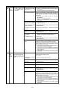
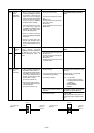
Short Circuit Detection Open Circuit Detection
TH11, TH12 240°C or higher (0.57 kΩ)15°C or lower (321 kΩ)
TH2 70°C or higher (1.71 kΩ) -40°C or lower (130 kΩ)
TH3 70°C or higher (1.71 kΩ) -40°C or lower (130 kΩ)
TH4 70°C or higher (1.71 kΩ) -40°C or lower (130 kΩ)
TH5 110°C or higher (0.4 kΩ) -40°C or lower (130 kΩ)
TH6 110°C or higher (0.4 kΩ) -40°C or lower (130 kΩ)
TH7 110°C or higher (1.14 kΩ) -40°C or lower (130 kΩ)
TH8 70˚C or higher (1.14 kΩ) -40°C or lower (130 kΩ)
TH9 70°C or higher (1.14 kΩ) -40°C or lower (130 kΩ)
THHS -40°C or lower (2.5 MΩ)
TH10 240°C or higher (0.57 kΩ) -15°C or lower (1656 kΩ)
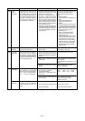
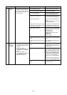
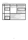
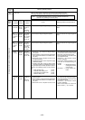
Short Detected Open Detected
TH11 110°C or more (0.4 kΩ) -40°C or less (130 kΩ)
TH12 110°C or more (0.4 kΩ) -40°C or less (130 kΩ)
TH15 70°C or more (1.14 kΩ) -40°C or less (130 kΩ)
TH16 70°C or more (0.4 kΩ) -40°C or less (130 kΩ)
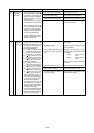
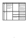
Check thermistor resistance.
Check lead wire biting.
Check broken cover.
Check coming off of pin at connector.
Check broken wire.
Check sensor sensing temperature. If
it deviates from the actual temerature
seriously, replace control panel.
1) Thermistor trouble.
2) Biting of lead wire.
3) Broken cover.
4) Coming off of pin at connector por-
tion, poor contact.
5) Broken wire.
6) Faulty thermistor input circuit of
control board.
5109
5110
5112
5111
CS circuit
(TH9)
Radiator
panel
(TH HS)
Compres-
sor shell
tempera-
ture
(TH10)
Liquid inlet
(TH11)
Bypass
outlet
(TH12)
Bypass
inlet
(TH15)
Intermedi-
ate section
(TH16)
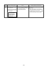
1. When short (high temp. inlet) or
open (low temperature inlet) of
thermistor is detected during
operation, error stop will be
commenced displaying “5111”
or “5112”, “5113” or “5114”, or
“5115” or “5116.
2. The above detectection is not
made during defrostig and 3-
minute after changing operation
mode.