


–57–
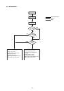
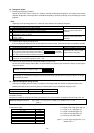
1 Detects the outdoor air temperature.
2 Performs fan control, liquid level
heater control, opening settings of
LEV for oil return and other functions.
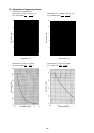
Thermistor
R0 = 15 kΩ
B1/80 = 3460
Rt =
15exp{3460( - )}
0°C: 15 kΩ
10°C: 9.7 kΩ
20°C: 6.4 kΩ
25°C: 5.3 kΩ
30°C: 4.3 kΩ
40°C: 3.1 kΩ
Resistance checkTH6
(Outdoor
temperature)
TH7
(Pipe inlet
heat ex-
changer
temperature)
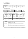
Outdoor unit
Name
Code
(Function)
Inspection methodApplicationProduct code Specification
1
273+t
1
273
1
273+t
1
273
1
273+t
1
273+120
1
273+t
1
323
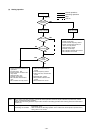
Resistance checkTH3
TH4
(Liquid level
detection)
TH5
(Pipe
temperature)
Detects liquid level of refrigerant inside
accumulator using the differences
among TH2, TH3, TH4.
1 Frequency control.
2 Controls defrosting during heating.
Resistance check
Conductivity test
using tester
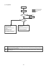
TH10
1) Detects the compressor shell
temperature.
2) Provides compressor shell over-
heating protection.
Inverter cooling fan control using THHS
temperature.
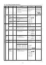
1 Capacity control of high/low
pressure bypass when starting and
stopping.
2
Discharge pressure rise suppression.
Switching of capacity control valve inside
No. 2 compressor (Switching between
full load operation and unload operation)
(only P500 YMF-C).
Capacity control and controlling the rise
of high-pressure (Back-up of frequency
control).
R120 = 7.465 kΩ
B25/120 = 4057
Rt =
7.465exp
{4057( - )}
20°C: 250 kΩ 70°C: 34 kΩ
30°C: 160 kΩ 80°C: 24 kΩ
40°C: 104 kΩ 90°C: 17.5kΩ
50°C: 70kΩ 100°C: 13.0 kΩ
60°C: 48kΩ 110°C: 9.8 kΩ
R50 = 17 kΩ
B25/120 = 4170
Rt =
17exp {4170 ( - )}
0°C: 181 kΩ
10°C: 105 kΩ
20°C: 64 kΩ
25°C: 50 kΩ
30°C: 40 kΩ
40°C: 26 kΩ
AC 220 to 240 V
Open: conducting
Close: not conducting
AC 220 to 240 V
Close: conducting
Open: not conducting
AC 220 to 240 V
Open: conducting
Close: not conducting
THHS inverter
heat sink tem-
perature
SV1
discharge-
suction
bypass
SV22
capacity
control (full
load)
SV32
capacity
control
(unload)
SV4a
discharge-
suction
bypas
s
TH9
Controls defrosfing during heating
1) Detects the CS circuit fluid tempera-
ture.
2) Calculates the refrigerant circulation
configuration.
R0 = 15 kΩ
B1/80 = 3460
Rt =
15exp{3460( - )}
0°C: 15 kΩ
10°C: 9.7 kΩ
20°C: 6.4 kΩ
25°C: 5.3 kΩ
30°C: 4.3 kΩ
40°C: 3.1 kΩ
Solenoid
valve