


–66–
77
77
7 TROUBLESHOOTING
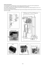
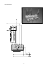
[1] Principal Parts
Pressure Sensor
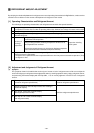
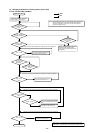
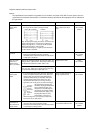
(1) Judging Failure
1) Check for failure by comparing the sensing pressure according to the high pressure/low pressure pressure sensor
and the pressure gauge pressure.
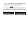
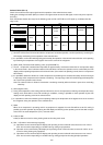
Turn on switches 1, 3, 5, 6 (High) and 2, 4, 5, 6 (Low) of the digital display select switch (SW1) as shown below, and
the sensor pressure of the high pressure/low pressure sensors is displayed digitally by the light emitting diode LD1.
High Pressure
Low Pressure
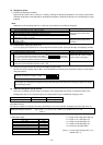
1 In the stopped condition, compare the pressure readings from the gauge and from the LD1 display.
(a) If the gauge pressure is 0~1 kg/cm
2
G (0.098MPa), the internal pressure is dropping due to gas leakage.
(b) If the pressure according to the LD1 display is 0~1 kg/cm
2
G (0.098MPa), there is faulty contact at the connec-
tor, or it is disconnected. Proceed to 4.
(c) If the pressure according to the LD1 display is 32 kg/cm
2
G (3.14MPa) or higher, proceed to 3.
(d) If other than (a), (b) or (c), compare the pressure readings during operation. Proceed to 2.
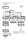
2 Compare the pressure readings from the gauge and from the LD1 display while in the running condition.
(a) If the difference between the two pressures is within 1 kg/cm
2
G (0.098MPa), both the affected pressure sensor
and the main MAIN board are normal.
(b) If the difference between the two pressures exceeds 1 kg/cm
2
G (0.098MPa), the affected pressure sensor is
faulty (deteriorating performance).
(c) If the pressure reading in the LD1 display does not change, the affected pressure sensor is faulty.
3 Disconnect the pressure sensor from the MAIN board and check the pressure according to the LD1 display.
(a) If the pressure is 0~1 kg/cm
2
G (0.098MPa) on the LD1 display, the affected pressure sensor is faulty.
(b) If the pressure is 32 kg/cm
2
G (3.14MPa) (in the case of the low pressure sensor, 10 kg/cm
2
G (0.98MPa)) or
higher, the MAIN board is faulty.
4 Disconnect the pressure sensor from the MAIN board and short out the No. 2 and No. 3 pins of the connector
(63HS, 63LS), then check the pressure by the LD1 display.
(a) If the pressure according to the LD1 display is 32 kg/cm
2
G (3.14MPa) (in the case of the low pressure sensor,
10 kg/cm
2
G (0.98MPa)) or higher, the affected pressure sensor is faulty.
(b) If other than (a), the MAIN board is faulty.
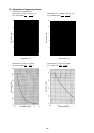
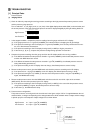
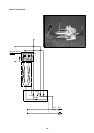
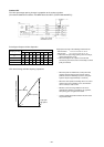
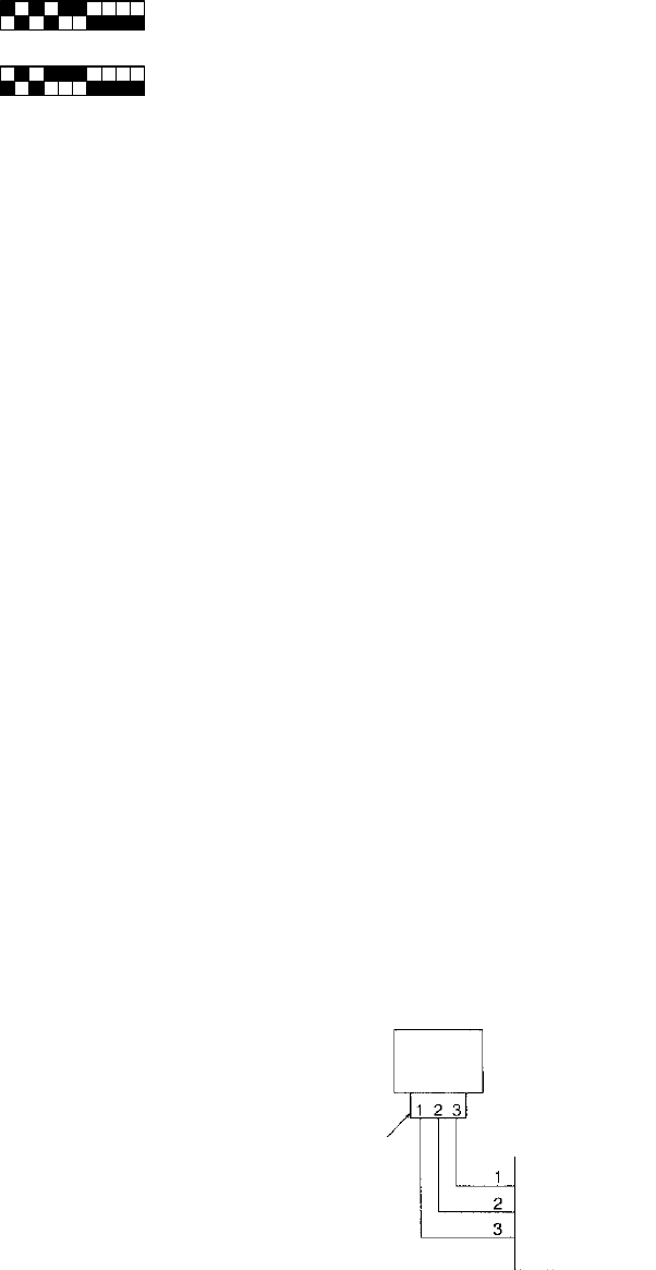
2) Pressure sensor configuration.
The pressure sensors are configured in the circuit shown in the figure at right. If DC 5 V is applied between the red
and black wires, a voltage corresponding to the voltage between the white and black wires is output and this voltage
is picked up by the microcomputer. Output voltages are as shown below.
High Pressure 0.1 V per 1 kg/cm
2
G (0.098MPa)
Low Pressure 0.3 V per 1 kg/cm
2
G (0.098MPa)
12345678910
ON
12345678910
ON
Connector
Vout 0.5~3.5 V
GND (Black)
Vout (White)
Vcc (DC5V) (Red)
63HS/
63LS