


–61–
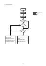
3) Check the refrigerant volume by LED monitor display using the LED.
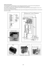
Set the LED monitor display switch (SW1) as shown below and check the past information (history) concerning the
refrigerant volume.
Set SW1 as shown in he figure at right.
If LD3 lights up, it indicates the refrigerant charge abnormal delay state just before emergency stop due to refriger-
ant overcharge (1500).
In the calculation results, round up fractions smaller than 0.01 kg. (Example: 18.54 kg → 18.6 kg)
L
1: Length of ø25.4 high press pipe (m)
L2: Length of ø12.7 liquid pipe (m)
L3: Length of ø9.52 liquid pipe (m)
L
4: Length of ø6.35 liquid pipe (m)
α1:refer to the calculation table.
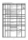
Judgment
Refrigerant volume tends toward
insufficient.
Refrigerant volume tends toward
overcharge.
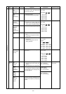
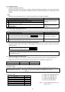
Check Items Judgment
12345678910
ON
Condition
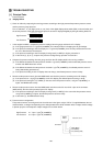
1 Discharge temperature is high. (125°C or higher)
2 Low pressure saturation temperature is extremely low.
3 Inlet superheating is high (if normal, SH = 20 deg. or lower).
4 Shell bottom temperature is high (the difference with the low pressure saturation
temperature is 70 deg. or greater)
5 Shell temperature is low (the difference with the low pressure saturation temperature is
10 deg. or lower).
6 Liquid level AL = 2
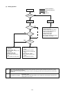
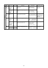
Normal if the resistance is 2.8 kΩ ± 7 %.
Normal if AC 198 ~ 264 V is output
together with the LED lighting.
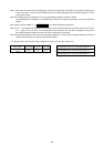
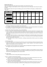
1 Liquid Heater Disconnection Check
2 Liquid Heater Output Check
Turn 1 ON on the LED monitor display switch (SW1)
12345678910
ON
, and output
the signal for the heater relay to LED 5, then check the voltage of the heater terminal (AC
198 ~ 264 V) (leave the heater connections as they are).
3 Use the LED monitor display to check if there is misalignment between the actual
temperature and the detected temperature of TH2 ~ TH4.
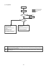
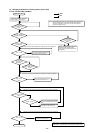
(2) Refrigerant Volume
1) Checking the Operating Condition
Operate all the indoor units in cooling or in heating, checking the discharge temperature, sub-cooling, low pressure
saturation temperature, inlet temperature, shell bottom temperature, fluid level, fluid step, etc. and rendering an overall
judgment.
Note:
Depending on the operating state, AL = 0 does not mean that there is insufficient refrigerant.
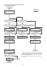
2) Cautions When Judging the Liquid Level
If you are judging the liquid level, be sure the liquid level sensor function (sensor and heater) are operating normally.
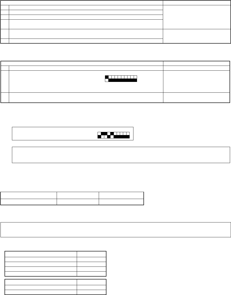
(α Calculation Table)
Total Capacity of Connected Indoor Units α1
161 ~ 330 2.0 kg
331 ~ 480 2.5 kg
481 ~ 630 3.0 kg
631 ~ 4.0 kg
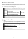
(3) Additional Refrigerant Charge Volume
At the time of shipping from the factory, the outdoor unit is charged with the amount of refrigerant shown in the
following table, but since no extension piping is included, please carry out additional charging on-site.
Additional Refrigerant Volume (kg) = (0.31 × L1) + (0.12 × L2) + (0.06 × L3) + (0.024 × L4) + α1 + α2
(Note 1)
Calculation Formula
Calculate the additional refrigerant volume by calculating the size of the extension liquid piping and its length (units: m).
Outdoor Unit Model PURY-P400YMF-C PURY-P500YMF-C
Refrigerant Charge Volume 20 kg 22 kg
α2
BC controller (master) only 0 kg
BC controller (slave) connected 3.0 kg
(Note 1) : In case high press pipe size (L1) is
ø22.22, 0.25 × L1.