


–114–
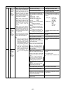
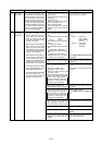
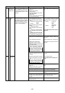
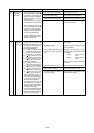
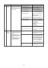
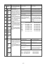
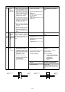
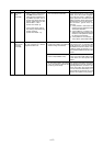
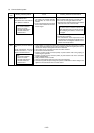
Checking code Meaning, detecting method Cause Checking method & Countermeasure
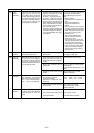
4240
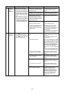
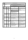
4250
Over loard
protection
IPM alarm
output /
Bus voltage
abnormality
If IAC 32 Arms is detected con-
tinuously for 10 minutes during op-
eration of the inverter after 5 or
more seconds have passed since
the inverter started.
1 If over current, overheat or
undervoltage of drive cirduit is
detected by IPM during inverter
operation.
[Inverter error detail : 1]
2 If VDC 300 or VDC 760V
is detected during inverter op-
eration.
[Inverter error detail : 1]
3 If IAC 39Arms is detected
during inverter operation.
[Inverter error detail : 11]
1) Air passage short cycle.
2) The heat exchanger is clogged.
3) Power supply voltage.
4) External air temperature.
5) Capacity setting error.
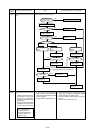
6) The solenoid valves (SV1, 2) are
defective, or the solenoid valve
drive circuit is defective.
7) The wiring is defective.
8) Fan motor (MF) operation is defec-
tive.
9) The inverter/compressor is defec-
tive.
1) The power supply voltage is abnor-
mal.
2) The wiring is defective.
3) The inverter / compressor is defec-
tive.
Is the unit’s exhaust short cycling?
Clean the heat exchanger.
If the power supply voltage is less than
342 V, it is outside specifications.
If the external air temperature is over
43°C it is outside the specifications.
• Is the indoor unit capacity total cor-
rect?
• Are the outdoor/indoor unit capac-
ity settings correct?
To judge failure of the solenoid valve,
go to “Individual Parts Failure Judg-
ment Methods” for the “Solenoid Valve.”
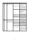
Check 1 connections, 2 contact at the
connectors and 3 for broken wires in
the following wiring.
TB1A~NF~TB1B
TB1B~FANCON board~CN04
CNMF~MF
TB1B~CNTR1
CNFC1~CNFC2
Go to “Treating Fan Motor Related
Trouble.”
Go to “Treating Inverter/Compressor
Related Trouble.”
• Check if an instantaneous stop or
power failure, etc. has occurred.
• Check if the voltage is the rated
voltage value.
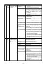
Check 1, the connections, 2, contact
at the connectors, 3 tightening torque
at screw tightened portions, 4, wiring
polarities, 5, for broken wires, and 6,
for grounding in the following wiring.
TB1A~NF~TB1B, TB1A~DS~[52C,
R1, R5]~[C2, C3]~IPM Wiring
CNDC1 (G / A) ~ CNVDC (INV) Wir-
ing
* Check if the wiring polarities are as
shown on the wiring diagram plate.
Go to “Treatment of Inverter/Compres-
sor Related Trouble.”