


Installation and Service Manual
ENERGY SAVING
RECOMMENDATIONS
1. Keep the pool covered when not in use. This will cut heating
cost, reduce water evaporation, conserve chemicals and reduce
load on the filtering system.
2. Reduce pool thermostat to 78°F or lower.
3. Use an accurate pool thermometer to monitor water
temperature.
4. Use a time clock to start filter pump no earlier than 6 a.m.
during pool season. This is the time when nightly heat loss
stabilizes.
5. Turn the pool heater “OFF” and drain during long periods when
the pool will not be used (winter, vacations, etc).
6. Follow a regular program of preventative maintenance for your
pool heater each new swimming season. Check heat exchanger,
controls, burners and operation of the pool heater.
7. For pools used only on weekends, the thermostat may be set
lower than 78ºF during the week. Lower setting to a range that
can be easily achieved in one day's operation of the pool heater.
SEQUENCE OF OPERATION
OVERVIEW
This sequence of operation can be considered the order of events in
sequential order that occur after the pool heater has received a call
for heat. The process begins with 120VAC power entering the pool
heater and ends with the pool heater going into an idle state after
completion of a successful call for heat.
Note:
The following
descriptions do not include remotely connected devices that may
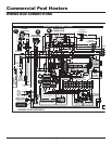
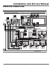
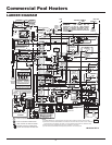
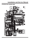
be connected to the pool heater. Refer to the wiring diagram for
actual point to point wiring connections that show power delivery.
1. Place the POWER switch in the “ON” position.
2. 120VAC power is supplied to the control transformer along with
L1 and F1 on the ignition module.
3. 24VAC is supplied to the adjustable high limit control.
4. 24VAC is then supplied to the 110°F mixed water limit control
and onto the 200°F fixed limit control.
5. If equipped, 24VAC is supplied to a low water cut-off and then
to the optional high and low gas pressure switches.
6. 24VAC is supplied to the terminal strip and onto the switching
contacts of the digital temperature control.
7. The digital temperature control will then call for heat.
8. 24VAC is then supplied to the water pressure switch and the
flow switch (if equipped).
9. 24VAC is then supplied to the TH terminals on the ignition
module.
10. As power is applied to the TH terminals on the ignition
module, 120VAC is switched from the F2 terminal to start the
combustion air fan(s).
11. 24VAC is supplied to the C terminal of the air pressure switch.
As the low air switch makes, power is supplied to the optional
louver/venter enable contact relay.
12. 24VAC is then supplied to the PS terminals on the ignition
module.
13. The combustion air fan operates for the pre-purge period.
14. At the end of the pre-purge period, 120VAC is applied to the
hot surface igniter and the trial for ignition light.
15. The hot surface igniter proves 1800°F (982°C) ignition
temperature by the current draw through the ignition module.
16. The ignition module supplies voltage to the MV terminals onto
the gas valve(s).
17. The first stage gas valve opens and supplies gas to the orifice
inlet to pre-mix.
18. The gas/air mixture is forced into the burner and out of the
burner ports under pressure.
19. The hot surface igniter lights the gas/air mixture and then
serves as a flame sensor to prove main burner flame by
rectification.
20. Burners for all stages are now firing at rated input on the
500,000 through 750,000 Btu/hr models.
21. On the 990,000 through 2,070,000 Btu/hr models
approximately 50% of the input is now energized.
22. 24VAC is supplied to a digital temperature control which times
out and then energizes the next 50% of the gas valves.
23. The remaining gas valves open and supply gas to the orifice
inlet to pre-mix.
24. The gas/air mixture is forced out of the burner ports and light
by carry-over from the burners currently firing.
25. The heater is now firing at full rated input.
HEAT TRANSFER PROCESS
26. Heated products of combustion pass over the heat exchanger
transferring heat to the water.
27. The rate of flue product movement is controlled by “V” baffles
on the heat exchanger to maximize heat transfer.
28. Flue products pass into the flue collector and are exhausted
from the unit.
END OF SEQUENCE
29. Set point temperature for the pool water is satisfied.
30. Power to the gas valves is turned “OFF”.
31. The combustion air fan runs for a 30 second post purge timing
and turns “OFF”.
32. The unit is now in a Standby Mode waiting for the next “Call
for Heat”.
51