


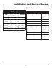

Installation and Service Manual
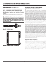
Combustion Air Fans
Both the 500,000 - 750,000 Btu/hr models and the 990,000 -
2,070,000 Btu/hr models use a fan-assisted combustion process. The
500,000 - 750,000 Btu/hr models have one fan
and the 990,000 - 2,070,000 Btu/hr models use two fans to supply
combustion air to the burners.
Fan Cleaning
Check each combustion air fan every six months. Clean the fan as
required when installed in a dusty or dirty location. Oiling is not
required.
Combustion Air Fan Adjustment
The combustion air fans are factory pre-set and should not need
adjustment in most cases. Follow the steps below to adjust the fan
if a continuous Low Air status code occurs.
Note:
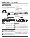
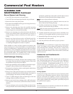
On the 500,000 - 750,000 Btu/hr models the air shutter is
adjusted on the side of the fan duct as depicted in Figure 52. On the
990,000 - 2,070,000 Btu/hr models the air shutter is adjusted on the
rear of the fan duct as depicted in Figure 54.
1. Check for proper installation and draft in the venting system.
Correct as required.
2. The following pressure settings are for installations up to 4000
feet altitude. Contact the factory for high altitude air pressure
settings.
Adjusting Differential Air Pressure
The following is a recommended method for setting the differential
air pressure (ΔP) for each fan.
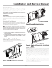
M
O
R
E
AIR
LESS AIR
AIR SHUTTER
Figure 52 – Adjusting Air Shutter 500,000 - 750,000 Btu/hr
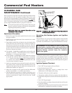
Figure 53 – Loosening Fan Transition Box Screws
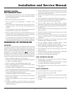
Figure 54 – Adjusting Air Shutter 990,000 - 2,070,000 Btu/hr
Models
Set-Up Procedure
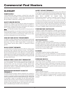
Beside the fan duct is an air pressure switch with a large and a small
tube delivering pressure from points inside the pool heater (see
Figure 55). The pressure in the large tube is the chamber pressure.
The pressure in the small tube is the burner pressure. They act
together to make the pressure switch. By disconnecting the caps
from the tees in the pressure switch hoses and connecting them to
either side of a manometer, you can read the differential pressure to
the switch.
The left pressure tapping connection on the manometer connects to
the tee in the tubing from the pool heater front chamber and the
right pressure tapping connection on the manometer connects to
the tee in the small tubing from the burner.
49