


11
Installation and Service Manual
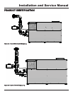
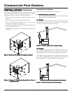
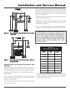
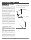
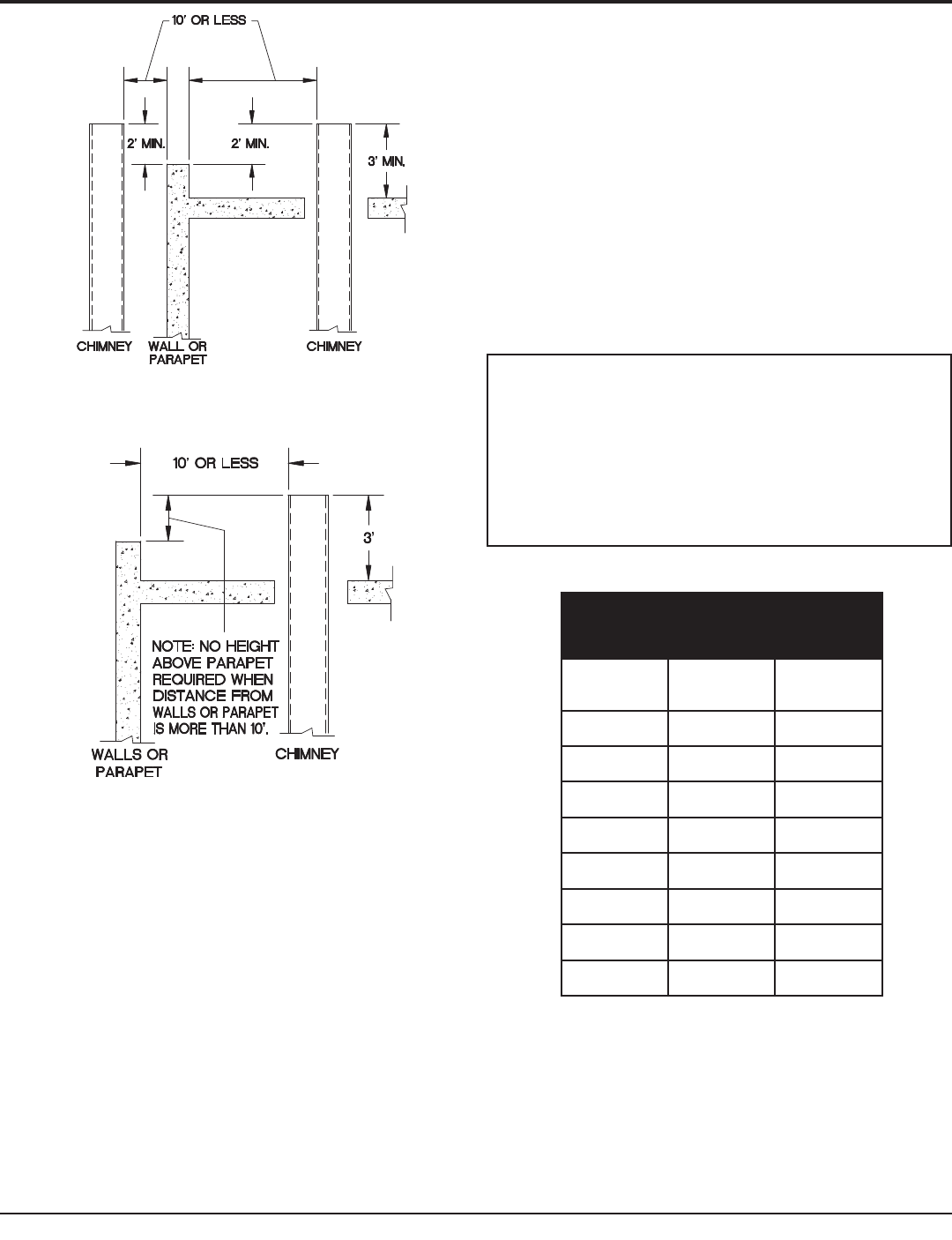
Figure 12 – Vent Termination from Flat Roof 10' or Less from
Parapet Wall
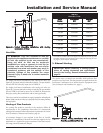
Figure 13 – Vent Termination from Flat Roof More Than 10'
from Parapet Wall
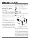
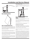
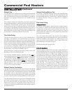
Sidewall Vent Termination Clearances and
Location
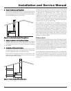
Locate the bottom of the vent terminal at least 12 inches (30cm)
above grade and above normal snow levels. Locate the bottom of
the vent terminal at least 7 feet (2.13m) above grade when located
adjacent to public walkways. Do not terminate directly above a
public walkway.
Do not terminate the venting system in a window well, stairwell,
alcove, courtyard, or other recessed area. Do not terminate the
venting system below grade.
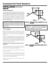
Locate vent termination at least 3 feet (0.91m) from an inside corner
of an L-shaped structure.
Provide a minimum clearance of 4 feet (1.2m) horizontally from
electric meters, gas meters, regulators, and relief equipment. Never
locate the vent cap above or below electric meters, gas meters,
regulators, and relief equipment unless a 4 foot (1.2m) horizontal
clearance is maintained.
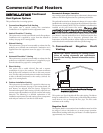
Terminate the venting system at least 3 feet (0.9m) above any forced
air inlet within 10 feet (3.05m).
Terminate the venting system at least 4 feet (1.2m) below, 4 feet
(1.2m) beside, or 1 foot (30cm) above any door, window, or gravity
air inlet into any building.
Locate vent termination at least 8 feet (2.4m) horizontally from any
combustion air intake located above the sidewall termination cap.
ƽ CAUTION: Pool heaters which are shut down or
will not operate may experience freezing due to
convective air flow in the flue pipe, through the air
inlet, or from negative pressure in the equipment
room. In cold climates, operate pump continuously
to help prevent freezing of pool heater water.
Provide proper freeze protection. See Freeze
Protection, page 7.
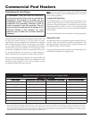
* Minimum diameter for air inlet pipe. Installer may increase diameter
one pipe size for ease of installation, if needed. Refer to the National
Fuel Gas Code (ANSI Z223.1) Vent Tables for additional guidance on
vent sizing of fan assisted appliances.
TABLE - B
Flue and Air Inlet Pipe Sizes
Input
Btu / hr
Flue
Size
Air Inlet
Size*
500,000 6" 6"
650,000 8" 8"
750,000 8" 8"
990,000 10" 10"
1,260,000 12" 12"
1,440,000 12" 12"
1,800,000 14" 12"
2,070,000 14" 12"