


Installation and Service Manual
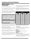
TABLE-F
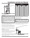
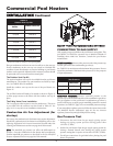
Horizontal DirectAire™ Kits
Input
Btu/hr
Kit*
500,000 HDK3031
650,000 HDK3032
750,000 HDK3032
990,000 HDK3037
1,260,000 HDK3038
1,440,000 HDK3038
1,800,000 HDK3039
2,070,000 HDK3039
*These kits include a sidewall venter assembly, vent termination, DV box
adapter, sidewall air inlet cap, and a barometric damper. See note on
page 12 concerning DV box adapter.
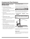
5. Direct Venting
IMPORTANT: Before installing a venting system,
follow all venting clearances and requirements
found in the Venting, General Information section,
page 10.
This option uses sealed AL29-4C vent materials for the flue outlet
piping and separate combustion air inlet piping. This system
terminates both the flue and combustion air inlet in the same
pressure zone. The flue outlet and combustion air intake may
terminate at either a sidewall or the rooftop.
To use the optional Direct Vent system, you must install specific
vent kits and venting materials. The following is a detailed
explanation of Direct Vent installation requirements, including the
components used and vent kit part numbers.
Flue Outlet Piping
Venting Guidelines
If using this venting option, a sealed AL29-4C venting system for
flue products is required on all models of this pool heater. This
venting system operates with a positive pressure in the vent. The
internal combustion air blowers generate this positive pressure
which operates the combustion process and also exhausts the flue
products from the building.
This vent system has specific vent material and installation
requirements. Only use listed sealed AL29-4C vent system materials
Follow all installation requirements. See TABLE–B, page 11 for
proper pipe size for your pool heater. A list of sealed AL29-4C flue
pipe manufacturers is located on page 22.
Seal all vent joints and seams gas-tight..
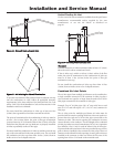
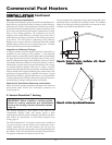
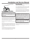
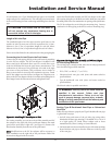
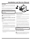
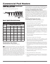
Drain Tee Installation
A drain tee must be installed in the vent pipe to collect and dispose
of any condensate that may occur in the vent system. The drain tee
must be installed as the first fitting after the horizontal ell on the
top of the unit (see Figure 23B). Plastic drain tubing, sized per the
vent manufacturer’s instructions, shall be provided as a drain line
from the tee. The drain tubing must have a trap provided by a
3" (7.6cm) diameter circular trap loop in the drain tubing. Prime
the trap loop by pouring a small quantity of water into the drain
hose before assembly to the vent. Secure the trap loop in position
with nylon wire ties. Use caution not to collapse or restrict the
condensate drain line with the nylon wire ties. The condensate drain
must be routed to a suitable drain for disposal of condensate that
may occur in the direct vent system. Refer to the condensate drain
installation instructions as supplied by the manufacturer of the vent
material.
ƽ WARNING: Do not combine the flue from this
unit with the vent from any other appliance. Do not
combine flues from multiple appliances into a
common vent. The flue from this unit must be a
dedicated stack.
Connect the flue vent directly to the flue outlet opening on the top
of the pool heater. Make the connections from the pool heater vent
to the outside stack as direct as possible with no reduction in
diameter. Provide adequate clearance to combustibles for the vent
connector and firestop. Follow the vent manufacturer’s instructions
when installing sealed AL29-4C vents and accessories, such as
firestop spacers, vent connectors, thimbles, caps, etc.
Provide adequate clearance to combustibles for the vent connector
and firestop.
When planning the venting system, avoid possible contact with
plumbing or electrical wiring inside walls, ceilings, and floors. Locate
the pool heater as close as possible to the chimney or gas vent. When
a vent system is disconnected for any reason, the flue must be
reassembled and resealed according to the vent manufacturer’s
instructions.
The installed length of flue from the pool heater to the outside point
of termination must not exceed 50 equivalent feet (15.2m). Subtract
5 feet (1.5m) of equivalent length for each 90° elbow. Subtract
2.5 feet (0.7m) of equivalent length for each 45° elbow.
21
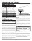
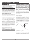
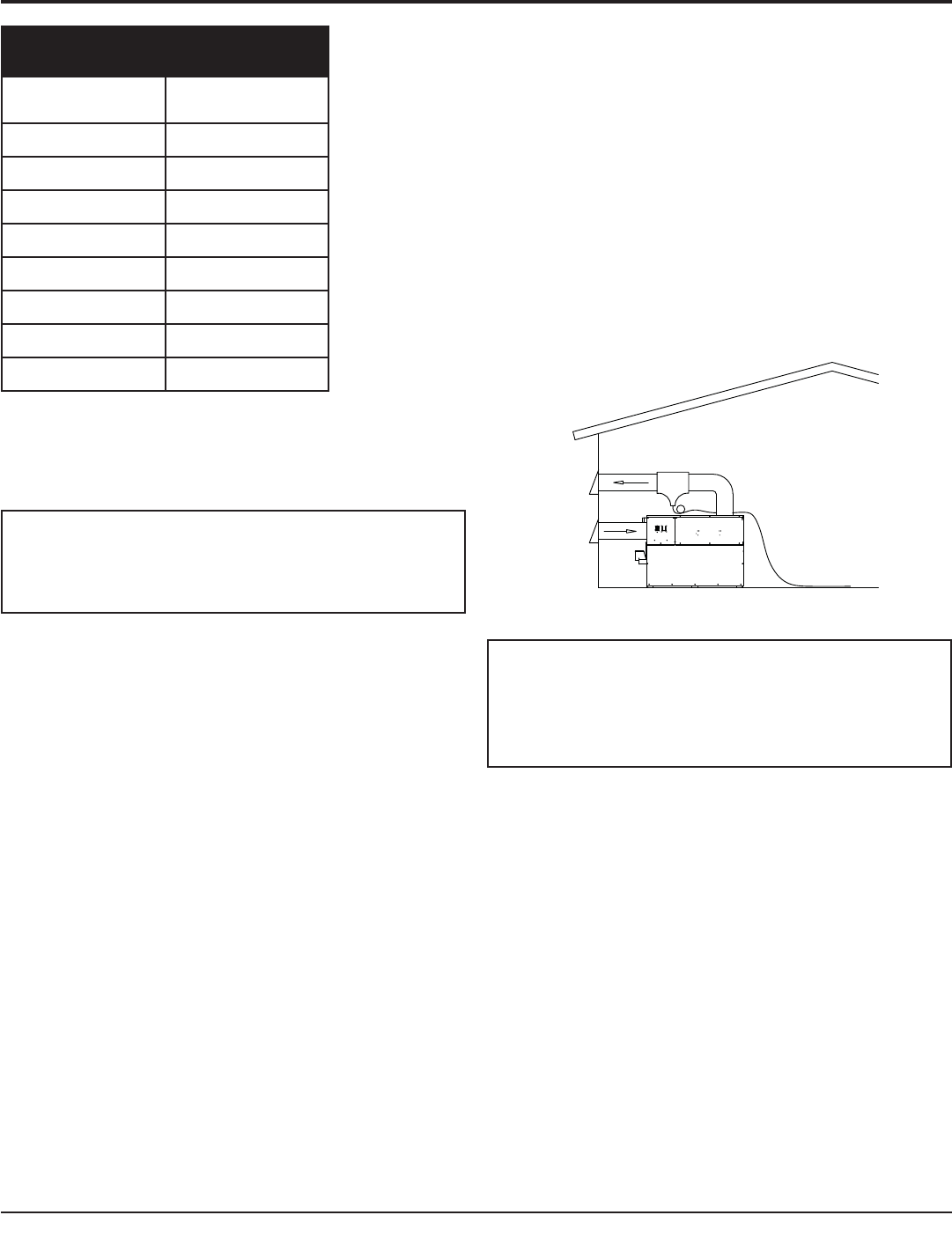
Figure 23B – Aire-Lock Direct Vent (Illustration with Sidewall
Vent and Sidewall Combustion Air)