


Commercial Pool Heaters
INSTALLATION
Continued
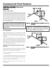
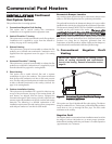
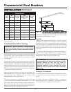
Sidewall Fan
The sidewall fan can be mounted on the inside/outside (depending
upon model) with a sidewall vent hood installed on the exterior
wall. The sidewall fan and accessories are included in a venting kit
provided by the appliance manufacturer. See TABLE–E for kit
numbers.
The venting kit includes the sidewall fan, vent hood, tapered vent
adapter, barometric damper, proving switch and all necessary relays
to interlock with the heaters control system. The tapered vent
adapter reduces the vent size at the inlet to the fan. There should be
no reduction in vent diameter from the pool heater’s flue outlet to
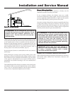
the sidewall fan. The barometric damper must be installed on the
flue and adjusted to supply a negative draft within the range of 0.04
to 0.08 inches w.c. while the pool heater is operating.
Flue Outlet Piping
With this venting option, you must use Type-B doublewall (or
equivalent) vent materials. Vent materials must be listed by a
nationally-recognized test agency for use as vent materials. Make
the connections from the pool heater vent to the sidewall fan/cap as
direct as possible with no reduction in diameter. Use the National
Fuel Gas Code venting tables for doublewall vent to properly size all
vent connectors and stacks. Follow the vent manufacturer’s
instructions when installing Type-B vents and accessories, such as
firestop spacers, vent connectors, thimbles, caps, etc.
When planning the venting system, avoid possible contact with
plumbing or electrical wiring inside walls.
The maximum installed length of sidewall vent pipe with
an
induced draft fan must not exceed 100 feet (30.5m) on the 500,000
- 2,070,000 Btu/hr models.
Note:
Models 990,000 - 2,070,000 are
not approved for sidewall venting without a fan. The maximum
installed length of sidewall vent pipe without
an induced draft fan
must not exceed 50 feet (15.2m) on the 500,000 - 750,000 Btu/hr
models. Subtract 5 feet (1.5m) for each 90° elbow. Subtract
2.5 feet (0.7m) for each 45° elbow.
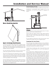
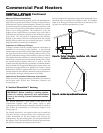
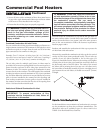
Sidewall Venting Termination
The sidewall vent cap must be installed on an exterior sidewall. The
sidewall fan/powered sidewall vent cap and accessories are included
in a venting kit which is furnished by the pool heater manufacturer
in accordance with CSA International requirements. This venting
kit includes the powered sidewall fan/cap, proving switch and all
necessary relays to interlock with the pool heater’s control system.
The sidewall fan/powered vent cap must be interlocked with the
pool heater’s control system to start the fan on a call for heat and
prove fan operation before the pool heater fires. Plug-in and
terminal strip connections are provided on the pool heater for easy
connection of the factory supplied vent kit and control package for
the sidewall vent fan.
Sidewall Venting Without Fan
For 500,000 - 750,000 Btu/hr models approved for sidewall venting
without an external power vent fan, you must install specific vent
kits and venting materials. The following is a detailed explanation
of Sidewall Venting Without an External Fan installation
requirements.
Flue Outlet Piping
Venting Guidelines
If using this venting option, a sealed AL29-4C venting system for
flue products is required on all models of this pool heater. This
venting system operates with a positive pressure in the vent. The
internal combustion air blowers generate this positive pressure
which operates the combustion process and also exhausts the flue
products from the building.
This vent system has specific vent material and installation
requirements. Only use listed sealed AL29-4C vent system materials.
Follow all installation requirements. See TABLE–B, page 11 for
proper pipe size for your pool heater. A list of sealed AL29-4C flue
pipe manufacturers is located on page 22.
Seal all vent joints and seams gas-tight.
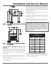
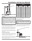
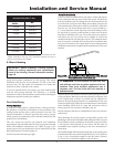
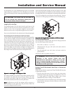
Drain Tee Installation
A drain tee must be installed in the vent pipe to collect and dispose
of any condensate that may occur in the vent system. The drain tee
must be installed as the first fitting after the horizontal ell on the
top of the unit (see Figure 22). Plastic drain tubing, sized per the
vent manufacturer’s instructions, shall be provided as a drain line
from the tee. The drain tubing must have a trap provided by a 3"
(7.6cm) diameter circular trap loop in the drain tubing. Prime the
trap loop by pouring a small quantity of water into the drain hose
before assembly to the vent. Secure the trap loop in position with
nylon wire ties. Use caution not to collapse or restrict the
condensate drain line with the nylon wire ties. The condensate drain
must be routed to a suitable drain for disposal of condensate that
may occur in the direct vent system. Refer to the condensate drain
installation instructions as supplied by the manufacturer of the vent
material.
18