


Commercial Pool Heaters
INSTALLATION
Continued
TABLE H
Outdoor Vent Cap Kits
Input
Btu/hr
Outdoor Vent Kit*
500,000 ODK3075
650,000 ODK3076
750,000 ODK3076
990,000 ODK3077
1,260,000 ODK3078
1,440,000 ODK3079
1,800,000 ODK3080
2,070,000 ODK3080
* These kits include an outdoor vent cap and gasket.
Flue gas condensate can freeze on exterior walls or on the vent cap.
Frozen condensate on the vent cap can result in a blocked flue
condition. Some discoloration to exterior building or pool heater
surfaces can be expected. Adjacent brick or masonry surfaces should
be protected with a rust resistant sheet metal plate.
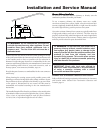
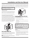
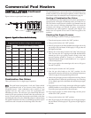
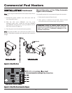
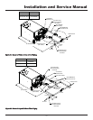
The Outdoor Vent Cap Kit
The optional outdoor vent cap kit is available from the pool heater
manufacturer. The outdoor cap part numbers are listed by input
size. See TABLE–H for kit numbers.
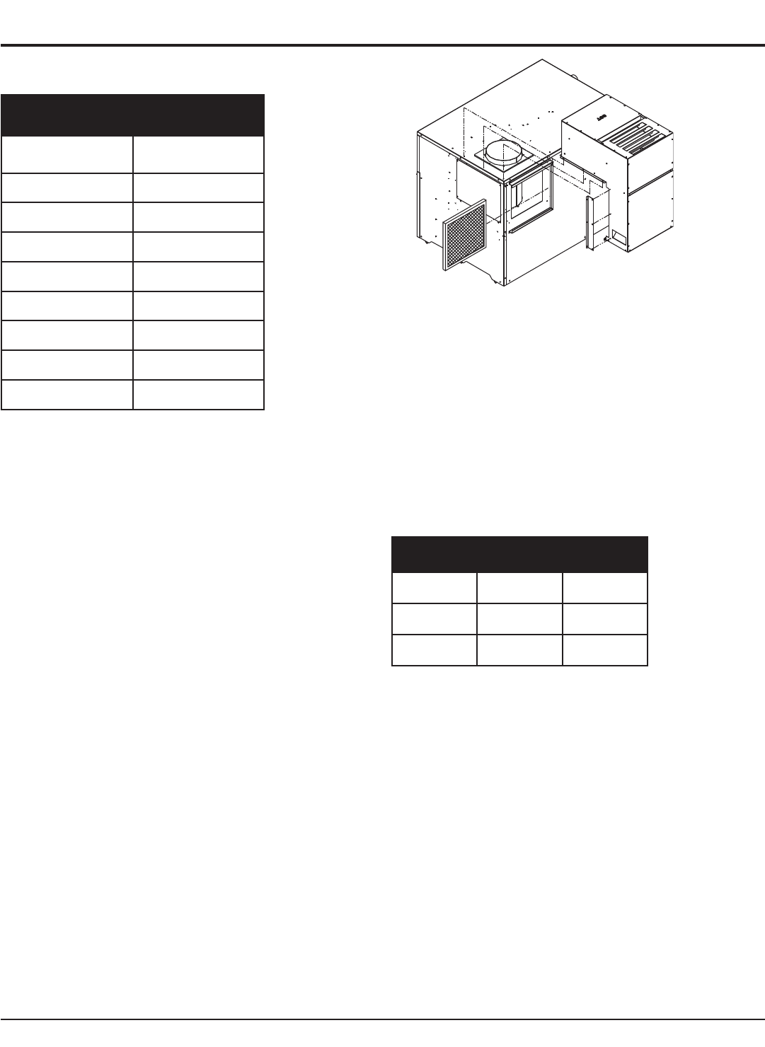
Install the outdoor vent cap on the rear of the pool heater, see
Figure 27.
The air filter bracket will need to be rotated as shown in Figure 27
to allow proper access to the filters with the outdoor vent cap in
place.
The 3-Way Valve Cover Installation
The 3-way bypass valve requires a cover for outdoor use. This cover
is provided with the outdoor vent kits listed in Table-H. See
page 31 for 3-way valve cover installation instructions.
Combustion Air Fan Adjustment (for
startup)
For startup, the combustion air fan shutter may require adjustment.
Should the combustion air fan shutter need adjusting refer to the
Adjusting Differential Air Pressure instructions located under the
Cleaning and Maintenance section on page 49 of this manual.
Note:
The manifold gas pressure can affect the differential air
pressure. Once the combustion air fan shutter has been adjusted,
confirm manifold gas pressure as described in the Gas Manifold
Pressure Adjustment section on page 30 of this manual.
Figure 27 – Outdoor Vent Cap Installed on Rear of Pool Heater
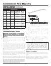
CONNECTING TO GAS SUPPLY
Only supply gas type specified on the pool heater’s rating plate. This
pool heater is orificed for operation up to 2000 feet altitude. If
installing above 2000 feet elevation, consult the pool heater
manufacturer.
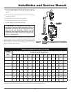
INLET PRESSURE: Measure inlet pressure at the inlet pressure tap
located upstream of the combination gas valve(s).
See TABLE–I for maximum and minimum inlet pressures. Do not
exceed the maximum. Minimum inlet pressure is for the purposes
of input adjustment.
TABLE-I
Inlet Pressure
Maximum Minimum
Natural Gas 10.5" w.c. 4.5" w.c.
LP Gas 13" w.c. 8" w.c.
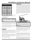
MANIFOLD PRESSURE: Measure manifold pressure at the
pressure tap on the downstream side of the combination gas valves.
The gas regulator on the pool heater’s combination gas valves is
preset at the factory to supply proper manifold pressure for normal
operation. See TABLE–L, page 31 for net manifold pressure settings.
If you must adjust regulator pressure, follow the instructions under
Gas Manifold Pressure Adjustment, page 30. Do not increase
regulator pressure beyond specified pressure setting.
Gas Pressure Test
1. Disconnect the unit from the gas supply piping system
during any piping system pressure testing greater than
1/2 PSIG (3.5kPa)
2. Isolate the pool heater from the gas supply piping system by
closing a manual shutoff valve during any piping system
pressure testing that is equal to or less than 1/2 PSIG (3.5kPa).
3. Test all gas connections for gas leaks before placing the pool
heater in operation.
26