


Commercial Pool Heaters
INSTALLATION
Continued
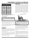
3. Secure all joints with a minimum of three sheet metal screws
or pop rivets. Apply aluminum foil duct tape or silicone sealant
to all screws or rivets installed in the vent pipe.
4. Ensure that the air inlet pipes are properly supported.
ƽ WARNING: Properly seal all joints and seams in
the inlet vent piping system. Failure to do so may
result in flue gas recirculation, spillage of flue
products, and carbon monoxide emissions. Carbon
monoxide poisoning can cause severe personal
injury or death.
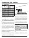
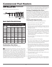
Combined Combustion Air Inlet Points
You can combine the air inlet pipes from multiple pool heaters to a
single common connection if the common air inlet pipe has a cross
sectional area equal to or larger than the total area of all air inlet
pipes connected to the common air inlet pipe.
Example: Two 8" (20.3cm) air inlet pipes (50.3 in
2
[324.5cm
2
]
area each) have a total area of 100.6 in
2
(645.2cm
2
), requiring a
12" (30.5cm) (113.1 in
2
[729.7cm
2
]) common air inlet pipe.
The air inlet point for multiple pool heater air inlets must be
provided with an exterior opening which has a free area equal to or
greater than the total area of all air inlet pipes connected to the
common air inlet. This exterior opening for combustion air must
connect directly to the outdoors. The total length of the combined
air inlet pipe must not exceed a maximum of 50 (15.2m) equivalent
feet. You must deduct the restriction in area provided by any screens,
grills, or louvers installed in the common air inlet openings and
some rooftop terminations. Screens, grills, or louvers installed in
the common air inlet can reduce the free area of the opening from
25% to 75% based on the materials used.
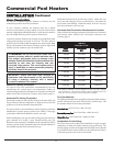
Vertical and Sidewall Combustion Air Inlet
IMPORTANT: To prevent recirculation of flue
products into the combustion air inlet, follow all
instructions in this section.
ƽ WARNING: Locate and install the combustion
air inlet termination correctly. Failure to do so can
allow the discharge of flue products to be drawn into
the combustion process. This can result in
incomplete combustion and potentially hazardous
levels of carbon monoxide in the flue products. This
will cause operational problems and the spillage of
flue products. Spillage of flue products can cause
personal injury or death due to carbon monoxide
poisoning.
You must locate the combustion air cap and the flue gas outlet on
the same rooftop surface (vertical direct vent system) or sidewall
surface (horizontal direct vent system) and in the same pressure
zone as the vent termination. Follow all clearance requirements
listed on pages 8 and 9.
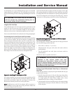
Purchase and assemble the combustion air inlet cap to protect the
air inlet from wind and weather.
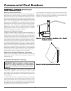
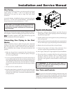
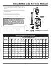
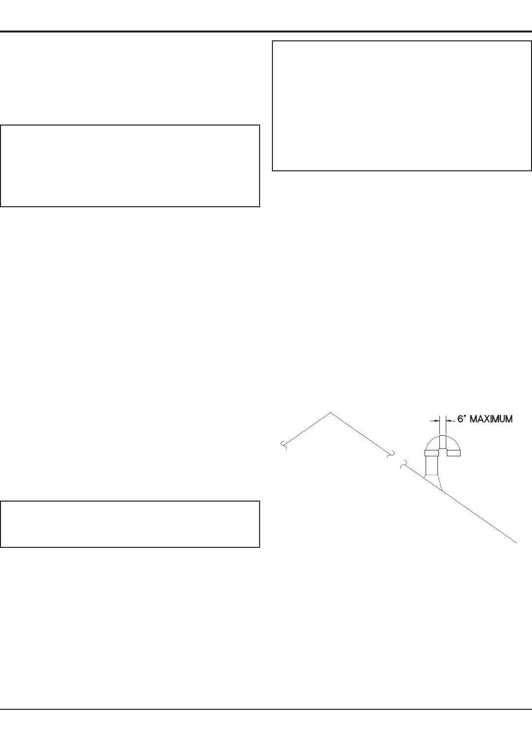
Alternatively, assemble the combustion air inlet cap for the vertical
rooftop air inlet from items purchased locally. The air inlet cap
consists of two 90° elbows installed to the air inlet pipe (see
Figure 26). Install the first 90° elbow on the rooftop at the highest
vertical point of the air inlet pipe. Install the second 90° elbow on
the horizontal outlet of the first elbow. The outlet of the second
90° elbow will be pointing down. You may use a 90° elbow and a
90° street elbow to make this assembly. If you use a straight piece of
pipe between the two 90° elbows, it should not exceed 6" (51mm)
in length.
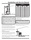
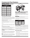
For horizontal direct vent termination of combustion air, you must
use the termination cap from the pool heater manufacturer. The
sidewall air inlet cap is available as part of a direct vent kit. See
TABLE–G for Horizontal Direct Vent Kits.
24
Figure 26 – Vertical Rooftop Air Inlet