


Installation and Service Manual
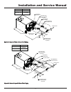
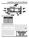
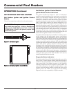
Relief Valve
COPPER OR CPVC
(SEE TABLE)
RECOMMENDED
ISOLATION VALVE
FLOWMETER
4" CPVC
4" CPVC
ALTERNATE POOL
RETURN SENSOR
LOCATION
3'
MINIMUM
110° LIMIT
TO POOL
FROM FILTER
OPTIONAL
POOL SUPPLY
SENSOR LOCATION
FACTORY POOL
RETURN SENSOR
LOCATION
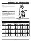
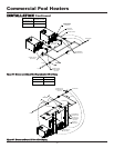
MODEL NO.
BYPASS PIPE SIZE
CP (N,L) 501 - 751
CP (N,L) 991 - 2071
2” MINIMUM
2 1/2” MINIMUM
Figure 38 - Multi-Stack Frame - Heaters are Beyond 15 feet from Pool Piping
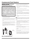
This pool heater is supplied with a relief valve(s) sized in accordance
with ASME Boiler and Pressure Vessel Code, Section IV. The relief
valve(s) is installed in the vertical position and mounted in the hot
water outlet. Place no other valve between the relief valve and the
pool heater. To prevent water damage, pipe the discharge from the
relief valve to a suitable floor drain for disposal when relief occurs.
Do not install any reducing couplings or other restrictions in the
discharge line. The discharge line will allow complete drainage of
the valve and line. Manually operate the relief valves at least once
a year.
ƽ CAUTION: Avoid contact with hot discharge
water.
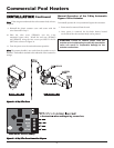
Automatic Chlorinator and Chemical
Feeders
All chemicals must be diluted into the pool water being circulated
through the pool heater. Any concentration of chlorine in the pool
heater can cause damage to the pool heater.
Do not place chlorine tablets or bromine sticks in the skimmer.
High chemical concentrations will result when the pump is not
running.
Chlorinator must feed downstream of the pool heater and have an
anti-siphoning device to prevent chemical back-up in the pool
heater when the pump is shut off.
IMPORTANT: High chemical concentrations from im-
properly adjusted feeders and Chlorinator can cause
rapid corrosion to the heat exchanger. This damage is
non-warrantable.
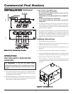
Water Flow Switch
A water flow switch is standard equipment. The wiring connection
installs the flow switch in the 24 VAC safety circuit to prove water
flow before main burner ignition. The standard flow switch is
installed in the outlet side of the piping loop when shipped from
the factory. These pool heaters require a sufficient flow of 26 GPM
to make the flow switch and start burner operation.
35