


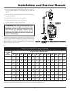
Installation and Service Manual
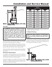
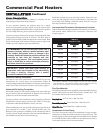
Vertical Combustion Air Inlet Clearances
You must locate the air inlet termination elbow at least 12" (30cm)
above the roof or above normal snow levels.
If the air inlet cap is within a 10 foot (3.05m) radius of the flue
outlet, the point of termination for the combustion air inlet cap
must be at least 3 feet (0.91m) below the point of flue gas
termination (vent cap).
Do not install the combustion air inlet cap closer than 10 feet
(3.05m) from an inside corner of an L-shaped structure.
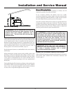
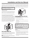
Horizontal Combustion Air Inlet Clearances
You must locate the horizontal air inlet termination point at least
12" (30cm) above grade and above normal snow levels.
If the air inlet cap is within a 10 foot (3.05m) radius of the flue
outlet, the point of termination for the combustion air inlet cap
must be at least 3 feet (0.91m) horizontally and 12 inches (30cm)
below the point of flue gas termination (vent cap). Do not install the
horizontal combustion air inlet cap above the flue outlet.
Do not install the combustion air inlet cap closer than 10 feet
(3.05m) from an inside corner of an L-shaped structure.
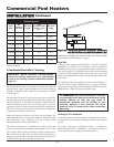
Multiple Sidewall Direct Vent Installations
The combustion air inlet caps for multiple pool heater installations
must maintain the same minimum clearance from the closest flue
vent cap as specified in single pool heater installations. You may
install multiple flue outlet caps side-by-side and multiple
combustion air inlet caps side-by-side, but the air inlet must always
be at least 3 feet (0.91m) horizontally and 12 inches (30cm) below
the closest flue outlet. Do not install combustion air inlet caps above
the flue outlets.
Maintain all clearances and installation requirements for multiple
pool heater installations.
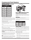
6. Outdoor Installation Venting
IMPORTANT: Before installing a venting system,
follow all venting clearances and requirements
found in the Venting, General Information section,
page 10.
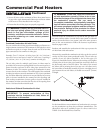
These pool heaters are self-venting and can be used outdoors when
installed with the optional outdoor cap. This cap mounts directly to
the top of the pool heater and covers the flue outlet and combustion
air inlet openings. No additional vent piping is required.
ƽ WARNING: Only install outdoor models
outdoors and only use the vent cap supplied by the
pool heater manufacturer. Personal injury or product
damage may result if any other cap is used or if an
outdoor model is used indoors. Properly install all
covers, doors and jacket panels to ensure proper
operation and to prevent a hazardous condition.
Combustion air supply must be free of contaminants (see
Combustion and Ventilation Air, page 7). To prevent recirculation
of the flue products into the combustion air inlet, follow all
instructions in this section.
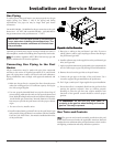
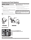
Outdoor Vent/Air Inlet Location
Keep venting areas free of obstructions. Keep area clean and free of
combustible and flammable materials. Maintain a minimum
clearance of 3" (76mm) to combustible surfaces and a minimum of
3" (76mm) clearance to the air inlet. To avoid a blocked air inlet or
blocked flue condition, keep the outdoor cap air inlet, flue outlet
and drain slot clear of snow, ice, leaves, debris, etc.
Do not install outdoor models directly on the ground. You must
install the outdoor pool heater on a concrete, brick, block, or other
non-combustible pad.
Do not locate the pool heater so that high winds can deflect off of
adjacent walls, buildings or shrubbery causing recirculation.
Recirculation of flue products may cause operational problems, bad
combustion or damage to controls. Locate unit at least 3 feet
(0.91m) from any wall or vertical surface to prevent wind conditions
from affecting performance.
Multiple pool heater outdoor installations require 48" (1.22m)
clearance between each vent cap. Locate the outdoor cap at least
48" (1.22m) below and 48" (1.22m) horizontally from any window,
door, walkway or gravity air intake.
Locate the pool heater at least 10 feet (3.05m) away from any forced
air inlet.
Locate pool heater at least 3 feet (0.91m) outside any overhang.
Clearances around outdoor installations can change with time. Do
not allow the growth of trees, shrubs or other plants to obstruct the
proper operation of the outdoor vent system.
Do not install in locations where rain from building runoff drains
will spill onto the pool heater.
25