


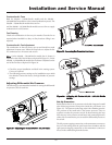
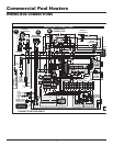
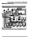
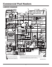

Commercial Pool Heaters
Appendix A
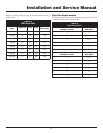
Unit Start Up Checklist
Ensure that the location and installation of the equipment is in
accordance with the installation manual, all local installation
requirements, and with the latest edition of the National Fuel Gas
Code, ANSI 223.1 and/or CAN/CGA-B149 Installation Code.
1. Measure the supply gas pressure. For natural gas models, the
supply gas pressure should be between 4.5" w.c. to 10.5" w.c.
For LP gas models, the supply gas pressure should be between
8" w.c. to 13" w.c. For a detailed procedure on measuring the
supply gas pressure, reference page 28 of this manual.
2. Measure the differential air pressure. The differential air
pressure for the 500,000 - 750,000 Btu/hr models should be
between 1.5" w.c. to 1.65" w.c. The differential air pressure for
990,000 - 2,070,000 Btu/hr models should be between 1.1" w.c.
to 1.3" w.c. Reference pages 49 and 50 of this manual for the
proper procedure for measuring the differential air pressure. If
an adjustment is necessary follow the procedure on page 50 of
this manual.
Note:
The combustion air fan(s) is factory preset and should not
need adjustment. However, due to installation and environmental
conditions adjustment of the air fan shutter(s) may be necessary at
start up.
3. Measure the net manifold gas pressure. For 500,000 - 750,000
Btu/hr models the net manifold gas pressure for natural gas
models should be 1.8" w.c For LP gas models the net manifold
gas pressure should be 4.6" w.c. For 990,000 - 2,070,000 Btu/hr
models the net manifold gas pressure for natural gas models
should be 1.2" w.c. For LP gas models the net manifold gas
pressure should be 4.6" w.c. For the proper procedure for
measuring net manifold gas pressure, reference page 30 of this
manual. If an adjustment of the net manifold gas pressure is
necessary, follow the procedure on page 30 of this manual.
Note:
The gas valves are factory preset and should not need
adjustment. However, due to installation and environmental
conditions adjustment of the gas valves may be necessary for
start up.
4. For negative draft vent systems, measure the draft in the
vent stack. The negative draft should be between -.02 w.c. to
-.08 w.c. Reference pages 10 - 26 of this manual to determine
which venting system is in use.
Note:
For positive pressure venting systems a draft measurement
is not required. Ensure that the vent length does not exceed the
maximum lengths listed in the Installation and Service Manual.
5. Adjust the temperature set point on the digital temperature
control to the desired pool temperature. Reference pages 40
and 41 of this manual for information regarding the operation
and adjustment of the digital temperature control.
6. A 3-way automatic bypass valve is factory installed to maintain
a minimum temperature of 130° to the inlet of the pool heater
to protect against flue gas condensation. Manual adjustment
of the valve is not required.
Note:
If the inlet temperature of the pool heater can not be
maintained at 130°, reference pages 33, 34, and 46 of this manual to
ensure that the pipe size and piping arrangements are correct.
If problems arise during the start up, reference the Installation and
Service Manual and/or consult the factory.
58