


15
Installation and Service Manual
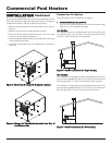
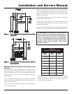
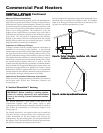
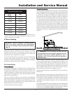
Connect the flue vent directly to the flue outlet opening on the top
of the pool heater. No additional draft diverter or barometric
damper is needed on single unit installations with a dedicated stack
and a negative draft within the specified range of 0.02 to 0.08 inches
w.c. If the draft in a dedicated stack for a single pool heater
installation exceeds the maximum specified draft, you must install
a barometric damper to control draft. Multiple pool heater
installations with combined venting or common venting with
other Category I negative draft appliances require each pool heater
to have a barometric damper installed to regulate draft within the
proper range.
Do Not connect vent connectors serving appliances vented by
natural draft (negative draft) to any portion of a mechanical draft
system operating under positive pressure. Connecting to a positive
pressure stack may cause flue products to be discharged into the
living space causing serious health injury.
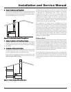
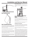
Flue Outlet Piping
With this venting option, you must use Type-B doublewall (or
equivalent) vent materials. Vent materials must be listed by a
nationally-recognized test agency for use as vent materials. Make
the connections from the pool heater vent to the outside stack as
direct as possible with no reduction in diameter. Use the National
Fuel Gas Code venting tables for doublewall vent to properly size all
vent connectors and stacks. Follow the vent manufacturer’s
instructions when installing Type-B vents and accessories, such as
firestop spacers, vent connectors, thimbles, caps, etc.
Provide adequate clearance to combustibles for the vent connector
and firestop.
When planning the venting system, avoid possible contact with
plumbing or electrical wiring inside walls, ceilings, and floors. Locate
the pool heater as close as possible to a chimney or gas vent.
Avoid long horizontal runs of the vent pipe, 90° elbows, reductions
and restrictions.
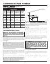
No additional draft diverter or barometric damper is required on
single unit installations with a dedicated stack and a negative draft
maintained between 0.02 to 0.08 inches w.c.
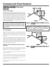
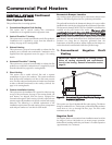
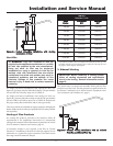
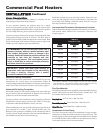
Common Venting Systems
You can combine the flue with the vent from any other negative draft,
Category I appliance. Using common venting for multiple negative
draft appliances requires you to install a barometric damper with each
pool heater. This will regulate draft within the proper range. You must
size the common vent and connectors from multiple pool heaters per
the venting tables for Type-B doublewall vents in the latest edition of
the National Fuel Gas Code, ANSI Z223.1 and/or CAN/CGA-B149
Installation Code.
Common venting systems may be too large when an existing pool
heater is removed.
At the time of removal of an existing pool heater, the following steps
shall be followed with each pool heater remaining connected to the
common venting system placed in operation, while other appliances
remaining connected to the common venting system are not in
operation.
1. Seal any unused opening in the common venting system.
2. Visually inspect the venting system for proper size and horizontal
pitch. Make sure there is no blockage or restriction, leakage,
corrosion and other unsafe conditions.
3. If possible, close all building doors and windows. Close all
doors between the space in which the appliances remaining
connected to the common venting system are located and other
building spaces.
4. Turn on clothes dryers and any other appliances not connected
to the common venting system. Turn on any exhaust fans, such
as range hoods and bathroom exhausts, so they will operate at
maximum speed. Do not operate a summer exhaust fan.
5. Close fireplace dampers.
6. Place in operation the unit being inspected. Follow the lighting
instructions. Adjust thermostat so pool heater will operate
continuously.
7. Test for spillage of flue gases at the draft hood/relief openings of
all appliances connected to the venting system after five minutes
of main burner operation.
8. After making sure that each appliance remaining connected to
the common venting system properly vents when tested as
above, return doors, windows, exhaust fans, fireplace dampers
and other gas burning appliances to their previous conditions
of use.
9. Correct any improper operation of the common venting system
so that the installation conforms to the latest edition of the
National Fuel Gas Code, ANSI Z223.1, in Canada, the latest
edition of CAN/CGA-B149 Installation Code for Gas Burning
Appliances and Equipment. When resizing any portion of the
common venting system, resize to approach the minimum size
as determined using the appropriate tables of the latest edition
of the National Fuel Gas Code, ANSI Z223.1, in Canada, the
latest edition of CAN/CGA-B149 Installation Code for Gas
Burning Appliances and Equipment.