


8
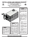
Commercial Pool Heaters
INSTALLATION
Continued
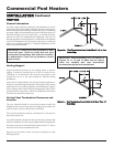
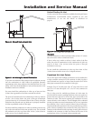
For convenience and flexibility, you can direct the combustion air inlet
from either the back or right side of the pool heater. To arrange the
combustion air inlet for side entry, follow the steps below.
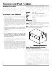
1. Remove the metal panel from the pool heater’s side wall (see
Figure 4).
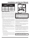
2. Remove screws from the air filter/bracket assembly.
3. Move the filter/bracket assembly from the rear of the pool
heater to the side opening (see Figure 5).
4. Attach the filter/bracket assembly to the pool heater’s side using
the pre-drilled screw holes.
5. Attach the metal panel to the rear combustion air opening to
seal it off.
Figure 5 – Moving Air Filter/Bracket Assembly from Rear of
Pool Heater to Side
Figure 4 – Metal Panel Covering Side Combustion Air Inlet
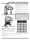
Combustion Air Options
This pool heater has four combustion air options.
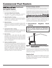
1. Outside Combustion Air, No Ducts
You can direct outside combustion air to this pool heater using
either one or two permanent openings.
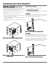
One Opening
The opening must have a minimum free area of one square inch
per 3000 Btu input (7cm
2
per kW). You must locate this opening
within 12" (30cm) of the top of the enclosure.
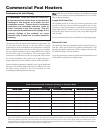
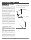
Two Openings
The combustion air opening must have a minimum free area of one
square inch per 4000 Btu/hr input (5.5cm
2
per kW). You must locate
this opening within 12" (30cm) of the bottom of the enclosure.
The ventilation air opening must have a minimum free area of one
square inch per 4000 Btu/hr input (5.5cm
2
per kW). You must locate
this opening within 12" (30cm) of the top of the enclosure.
Figure 6 – Outside Combustion Air - Single Opening
Figure 7 – Outside Combustion Air - Two Openings