


Installation and Service Manual
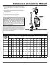
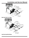
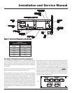
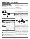
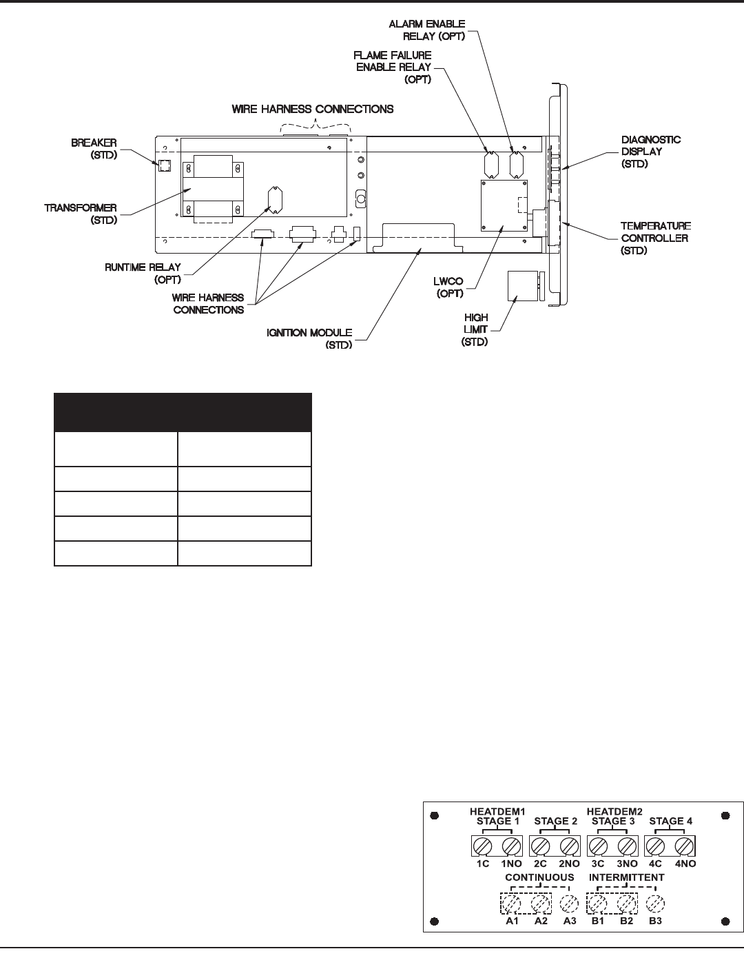
Figure 39 - Control Panel Component Location Drawing
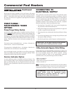
TABLE-M
Remote Wire Connection
Wire
Gauge
Maximum
Allowable Length
12 GA 100 ft.
14 GA 75 ft.
16 GA 50 ft.
18 GA 30 ft.
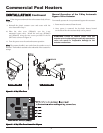
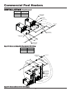
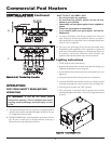
Terminal Strip Connection Options
The scenarios shown in Figures 40 A - C represent typical terminal
strip connection requirements. The terminal strips are located on
the left side of the pool heater under the electrical access panel.
Other applications may be accommodated, but must be addressed
individually.
Figure 40-A shows the position of the jumpers as shipped from the
factory for stand-alone operation of the pool heater.
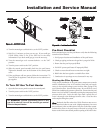
Figure 40-B shows connections to the terminal strip for Remote
ON/OFF control of the pool heater. The 1C-1NO jumper must be
removed when making these wiring connections. This remote
ON/OFF control will provide an Enable/Disable signal to the pool
heater and allow the pool heater to operate based on the set point,
until the remote ON/OFF signal is cancelled. If the remote ON/OFF
control is also an external pool temperature control, adjust the pool
heater’s pool return set point a few degrees higher than the external
pool temperature control’s set point. The pool heater temperature
control will then act as a backup to the external pool temperature
control.
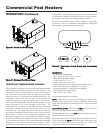
Figure 40-C shows the Continuous and Intermittent terminals.
External safety devices connected to these terminals will function to
protect the pool heater. Devices connected to the Intermittent
terminals (B1 and B2) are monitored only when there is an active
Call for Heat. Devices connected to the Continuous terminals (A1
and A2) are monitored continuously and will activate and alarm (if
the pool heater is equipped with the alarm option) anytime the
safety device senses an abnormal condition. An additional wire may
be field installed from these safety devices to terminals A3 or B3 (as
appropriate) to activate an audible alarm (if the pool heater is
equipped with the alarm option).
A.
37