


Commercial Pool Heaters
INSTALLATION
Continued
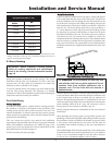
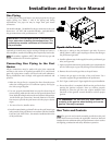
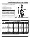
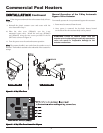
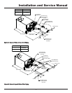
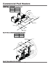
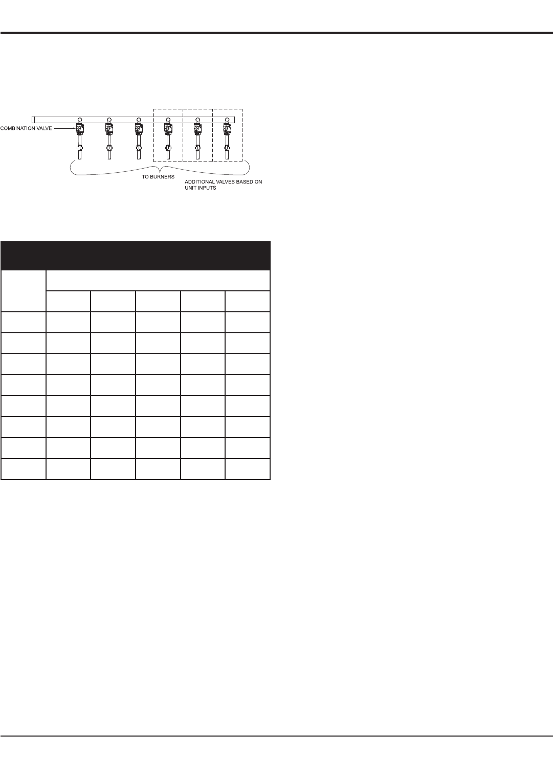
Figure 29 shows a typical pool heater gas train.
Figure 29 – Typical Pool Heater Gas Train Drawing
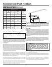
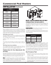
TABLE-J
Suggested Gas Pipe Size for Single Unit Installations
Btu/hr
Input
Distance From Meter (in feet)
0-50 51-100 101-200 201-300 301-500
500,000 1 1/4" 1 1/2" 2" 2" 2 1/2"
650,000 1 1/2" 2" 2" 2 1/2" 2 1/2"
750,000 1 1/2" 2" 2" 2 1/2" 3"
990,000 2" 2" 2 1/2" 2 1/2" 3"
1,260,000 2" 2 1/2" 2 1/2" 3" 3"
1,440,000 2 1/2" 2 1/2" 3" 3" 3 1/2"
1,800,000 2 1/2" 3" 3" 3 1/2" 3 1/2"
2,070,000 2 1/2" 3" 3" 3 1/2" 4"
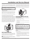
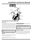
Combination Gas Valves
These pool heaters fire in a single stage of operation.
Note:
This pool heater incorporates a “soft start” feature which
lights approximately half of the burners before lighting the
remaining burners. Each combination valve consists of a gas
regulator and two valve seats to meet the requirements for
redundant gas valves. The valve has a gas control knob that must
remain in the open position at all times when the pool heater is in
service. The gas control valve has pressure taps located on the inlet
and discharge sides of the valve. Manifold pressure is adjusted using
the regulator located on the valve. A manifold gas pressure tap for
each burner stick is located on the discharge side of the valve.
The manifold pressure is preset at the factory and adjustment is not
usually required. If you must adjust regulator pressure, follow the
instructions under Gas Manifold Pressure Adjustment, page 30.
Venting of Combination Gas Valves
The combination gas valve/regulator used on these pool heaters is
equipped with an integral vent limiting orifice per ANSI Z21.78.
The vent limiter ensures that the volume of gas emitted from the
valve in the event of a failed gas diaphragm does not exceed the
maximum safe leakage rate allowed by agency requirements.
Combination gas valve/regulators equipped with integral vent
limiters are not required to have vent or relief lines piped to the
outdoors.
Checking Gas Supply Pressure
Use the following procedure to check gas supply pressure.
1. Turn the main power switch to the “OFF” position.
2. Turn gas valve knobs to the “OFF” position.
3. Shut off gas supply at the field-installed manual gas cock in the
gas piping to the pool heater. If fuel supply is L.P. gas, shut off
gas supply at the tank.
4. Remove the 1/8" hex plug, located on the “inlet” side of any gas
valve. You may also use a tapping on the field-installed main
manual gas cock or gas piping. Install a fitting in the inlet
pressure tapping suitable to connect to a manometer or
magnahelic gauge. Range of scale should be 14" w.c. or greater
to check inlet pressure.
5. Turn on gas supply at the manual gas cock, turn on L.P. gas at
the tank if required.
6. Turn the power switch to the “ON” position.
7. Turn the gas valve knobs to the “ON” position. Set the
temperature control to call for heat. See Operating Temperature
Control on page 40 for programming instructions.
8. Observe the gas supply pressure as all burners are firing. Ensure
that inlet pressure is within the specified range. See Connecting
To Gas Supply, page 26 for minimum and maximum gas supply
pressures.
9. If gas pressure is out of range, contact gas utility, gas supplier,
qualified installer or service agency to determine necessary steps
to provide proper gas pressure to the pool heater.
10. If gas supply pressure is within normal range, turn the power
switch to the “OFF” position.
11. Turn gas valve knobs to the “OFF” position.
12. Shut off gas supply at the manual gas cock in the gas piping to
the pool heater. If fuel supply is L.P. gas, shut off gas supply at
the tank.
28