


Commercial Pool Heaters
CLEANING AND
MAINTENANCE Continued
If the air pressure switch does not make within 60 seconds from the
time the fans turn ON, the ignition module will go into a soft
lockout period (approximately 5 minutes in duration) during which
time the fans are turned off and the module shows the Low Air flash
code. If necessary, soft lockout can be circumvented by cycling
power using the ON/OFF switch to cycle power to the unit.
Note:
If the pool heater has been firing recently, allow the pool
heater to cool for five minutes with the fans running before
beginning the adjustment procedure.
Retain the plastic caps removed from the tees for
reinstallation when complete.
Adjustment Procedure
1. Remove the upper front jacket panels from the unit to access
the upper chamber.
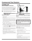
2. Slightly loosen screws that attach fan transition box to metal
base (see Figure 53).
3. Depending on model, the air shutter(s) may be located either
on the side or the rear of the fan duct. Locate the air shutter at
the side/rear of the fan duct (see Figure 52 and 54). Move the
air shutter towards the rear or left side of the unit to increase air
pressure. Move the air shutter towards the front or right side of
the unit to decrease air pressure.
4a.The 500,000 - 750,000 Btu/hr models have one fan with a side
mounted air shutter. The differential for these models is
nominally 1.5 - 1.65 inches water column.
4b.On the 990,000 - 2,070,000 Btu/hr models adjust the air shutter
on the left fan until the differential pressure is nominally
1.1 - 1.3 inches water column.
Note:
The air chamber pressure
is 1.2 inches water column for liquefied petroleum (L.P.) and
1.4 inches water column for natural.
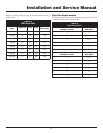
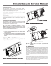
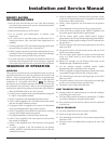
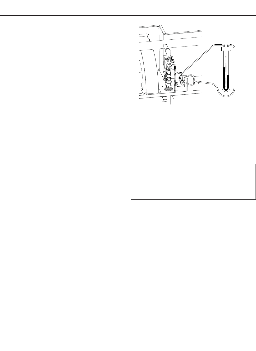
5. Attach one manometer hose to the barb located on the back of
the pressure switch. Attach the other manometer hose to the
capped tee barb spliced into the rubber hose running into the
combustion chamber (see Figure 55).
6. Adjust the air shutter on the right fan until the differential
pressure is nominally 1.1-1.3 inches water column.
7. Once the adjustment procedure is complete, reattach the cap to
the tee in the hose and the pressure switch and check all tubing
and wire connections for snug fit. Test fire the unit. Install
upper panels.
Figure 55 – Combustion Air Adjustment with a Manometer to
Set Differential Pressures
Servicing Hot Surface Igniter and Ignition
Module
This pool heater uses a proven hot surface ignition control module
and a hot surface igniter. The hot surface ignition module is not
repairable. Any modification or repairs will invalidate the warranty.
ƽ WARNING: Do not attempt to repair a faulty hot
surface igniter or ignition module. Any modification or
repairs may create hazardous conditions that result in
property damage, personal injury, fire, explosion
and/or toxic gases.
A faulty hot surface igniter or ignition module must be replaced
with an identical part. A specification igniter and ignition control
module for this specific pool heater is available from your local
distributor. Do not use general purpose field replacement ignition
modules or igniters.
Ignition System Checkout
1. Turn “OFF” the gas supply to the pool heater.
2. Turn the electric power “ON”.
3. Program the temperature control to settings above water
temperature or to the highest safe setting.
4. The igniter will cycle on trial for ignition.
5. The ignition module will lock out and turn the alarm light on.
6. Program the temperature control to the desired temperature set
point.
7. Turn “ON” the gas supply.
8. Press the module reset button (located on the front of the unit)
to reset the module.
9. If ignition system fails to operate properly, repair work must be
performed by a qualified serviceperson or installer.
50