


Installation and Service Manual
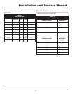
Code Sequence Condition
Constant ON System OK, no faults present.
Constant OFF Possible control fault, check power;
LED may be effective, do not
replace control if all operational
sequences function properly, see
TroubleShooting Guide.
One Flash Low Air, check air pressure switch and
hoses to pressure sensing points, fan,
venting and sealing of pressurized
chamber.
Note:
Brief flashing normal on fan start-up/proving.
Two Flashes Flame without call for heat, check for a
gas valve stuck in the open position, air,
venting, burners and the combustion
process. Fan will remain on.
Three Flashes Lockout due to flame failure, push reset
button on outer control panel after
correcting ignition problem. Initial heater
start up without properly bleeding air
from the gas line may require multiple
reset functions to achieve proper ignition.
Four Flashes Igniter failure, igniter will not maintain
minimum 2.75 amp current draw, caused
by low voltage, bad wiring/continuity,
high resistance or igniter failure.
Five Flashes Power supply problem, check for low
supply voltage or transformer output less
than 18VAC.
Six Flashes Replace ignition module, internal fault.
TABLE-N
Ignition Control Diagnostic Codes
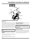
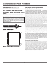
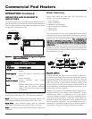
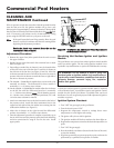
Access to Internal Control Panel
The control panel is accessed by turning the knurled knob located
at the bottom center of the exterior control panel. Pull the panel
out at the bottom. The door will tilt into unit until it comes free
from the outer top. The outer control panel has an overlay attached
to the exterior surface which indicates the function of each of the
pool heater’s indicating lights and a clear window to view the digital
temperature display from the temperature control. The thermostat
and diagnostic light board are mounted to the back of the control
panel door.
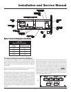
The control panel assembly is mounted on a slide out chassis to
allow easy access to the components on the panel. The control panel
contains the ignition module, transformer for the 24 VAC control
circuit, circuit breaker for the control circuit, switching relays for
component operation and wiring harness connections to the pool
heater’s components. The control panels are common and may be
switched between pool heaters for troubleshooting.
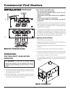
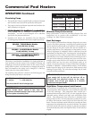
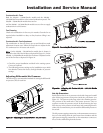
Removing the Control Panel
1. Pull the control panel out as far as it will go.
2. Remove the multi-pin connector blocks from the top and right
side of the control panel.
3. Use a 1/2" box wrench or socket wrench to remove the bolt on
the right side of the control panel.
4. Remove the entire control panel.
5. Reinstall the control panel in the reverse order.
Ignition and Control Timings
Proven Pilot Hot Surface Ignition System F-9 on 500,000 through
2,070,000 Btu/hr models with One Hot Surface Ignition Module.
Hot Surface Ignition Module Timings (Nominal)
Prepurge: 15 Seconds
Hot Surface Igniter Heat-up Time: 25 - 35 seconds
Main Burner Flame Establishing Period: 4 Seconds
Failure Response Time: 0.8 Seconds at less than 0.5 µA flame
current
Flame Current: 5 - 15 µA
Post-purge: 30 Seconds
Optional Pump Delay Timing: 30 Seconds after burner shutdown
ƽ CAUTION: Control panel is heavy and awkward
to handle when removed. Carefully support the
control panel when removing.
43