


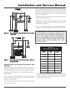

14
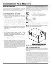
Commercial Pool Heaters
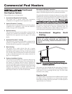
INSTALLATION
Continued
Vent System Options
This pool heater has six venting options.
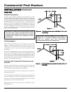
1. Conventional Negative Draft Venting
This option uses a vertical rooftop flue termination.
Combustion air is supplied from the equipment room.
2. Vertical DirectAire™ Venting
This option uses a vertical conventional vent for flue products.
Combustion air is supplied by a pipe from the sidewall or
rooftop. See page 16 for venting details.
3. Sidewall Venting
This option uses a powered vent assembly to exhaust the flue
products out a sidewall vent termination. Combustion air is
supplied from the equipment room. See page 17 for venting
details.
4. Horizontal DirectAire™ Venting
This option uses a powered vent assembly to exhaust the flue
products out a sidewall. Combustion air is supplied by a pipe
from the sidewall. See page 20 for venting details.
5. Direct Venting
This option uses a sealed AL29-4C flue and a separate
combustion air pipe to the outdoors. This system terminates
both the flue and combustion air inlet in the same pressure
zone. The flue outlet and combustion air intake may terminate
at either a sidewall (horizontal) or the rooftop (vertical). See
page 21 for venting details.
6. Outdoor Installation Venting
This option uses the installation of a special air inlet/vent cap
on top of the pool heater. See page 25 for venting details. All
pool heaters are shipped from the factory equipped for
conventional negative draft venting. All other optional vent
systems require the installation of specific vent kits and venting
materials. The following is a detailed explanation of the
installation requirements for each venting system, components
used and part numbers of vent kits for each model.
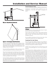
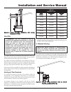
Barometric Damper Location
Any venting system option that requires a barometric damper must
adhere to the following directions for optimum performance.
The preferred location for the barometric damper is in a tee or collar
installed in the vertical pipe rising from the pool heater’s flue outlet.
The barometric damper MUST NOT be installed in a bull head tee
installed on the pool heater’s flue outlet. The tee or collar
containing the barometric damper should be approximately three
feet vertically above the connection to the pool heater’s flue outlet.
This location ensures that any positive velocity pressure from the
pool heater’s internal combustion fan is dissipated and the flue
products are rising due to buoyancy generated from the
temperature of the flue products. Adjust weights on the damper to
ensure that draft is maintained within the specified range.
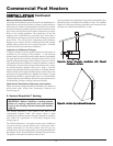
1. Conventional Negative Draft
Venting
IMPORTANT: Before installing the venting system,
follow all venting clearances and requirements
found in the Venting, General Information section,
page 10.
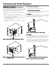
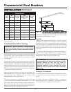
Figure 17 – Conventional Negative Draft Vertical Venting with
Combustion Air Louvers
This option uses Type-B doublewall flue outlet piping. The blower
brings in combustion air. The buoyancy of the heated flue products
cause them to rise up through the flue pipe. The flue outlet
terminates at the rooftop.
Negative Draft
The negative draft in a conventional vent installation must be within
the range of 0.02 to 0.08 inches w.c. to ensure proper operation.
Make all draft readings while the pool heater is in stable operation
(approximately 2 to 5 minutes).