


Installation and Service Manual
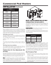
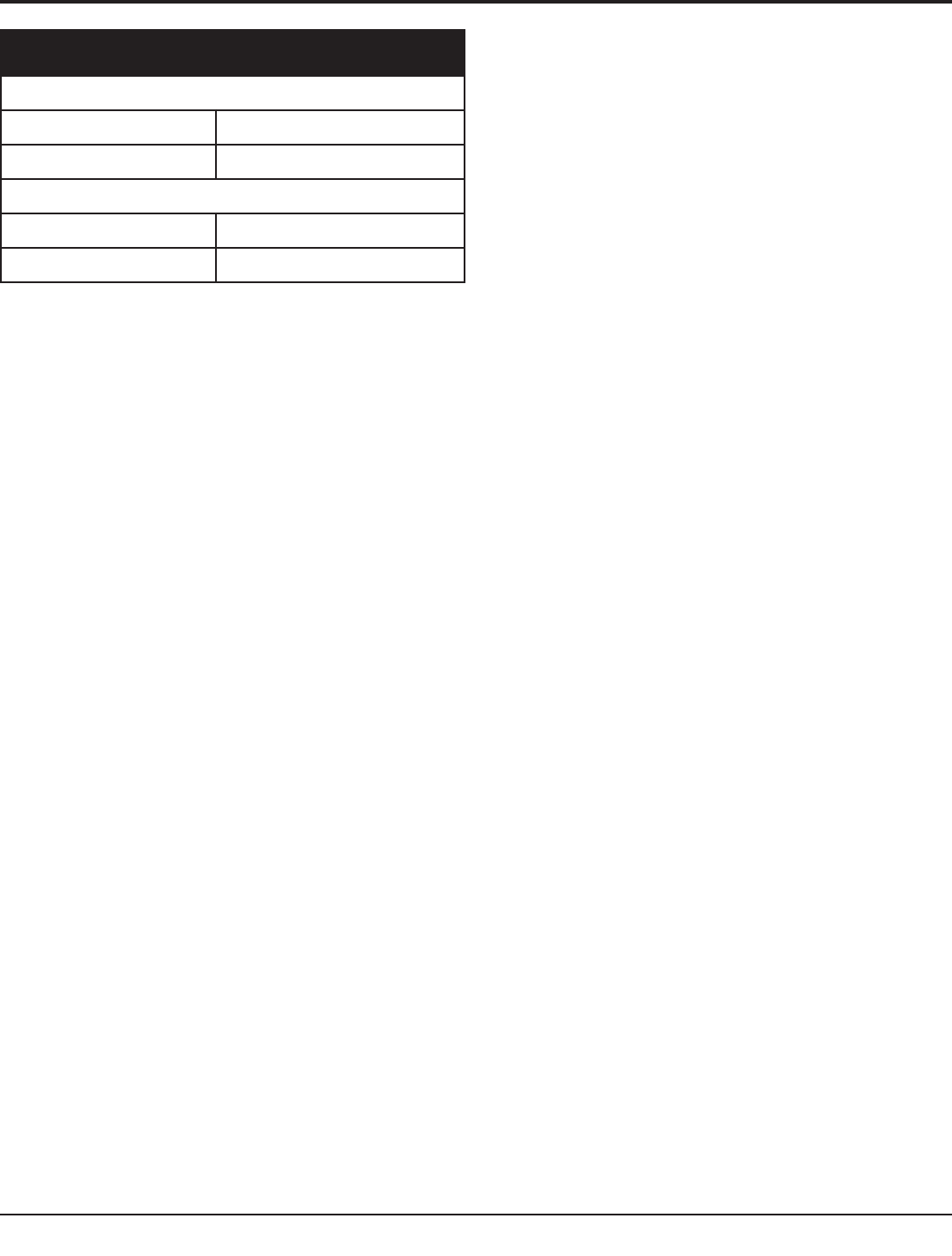
TABLE-L
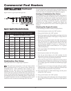
Net Manifold Pressure
500,000 – 750,000
Natural Gas 1.8" w.c.
LP Gas 4.6" w.c.
990,000 – 2,070,000
Natural Gas 1.2" w.c.
LP Gas 4.6" w.c.
*Net Manifold Pressure equals the measured manifold pressure minus
the chamber pressure. See Figure 31 to measure the Net Manifold Pressure.
POOL HEATER PIPING
INSTALLATION
Install piping from the filter system to the pool heater as shown in
the pool heater piping diagrams. See Figures 34 - 38. Minimum
pipe diameter to and from the installed pool heater to the filter
system piping on models 500,000 - 750,000 Btu/hr is 2" and on
models 990,000 - 2,070,000 Btu/hr the minimum is 2-1/2". The
piping from the filter system to the pool heater may be PVC, CPVC
or Copper Pipe. The piping from the pool heater back to the filter
system will carry water with temperatures in excess of 110°F and
must be CPVC or Copper Pipe. The temperature of the heated
water from the pool heater will be substantially cooled as it is mixed
back into the pool water from the filter system and returned to the
pool. The mix of heated water and pool water from the filtration
system should only be slightly warmer than the pool water before
the connections from the pool heater.
Auxiliary Mixed Water Limit Control
Ensure that the auxiliary 110°F mixed water limit control (and
optional pool supply sensor, if used) are installed in the filter system
piping. Install the auxiliary limit a minimum of three feet
downstream from the point where the heated water from the pool
heater is added to the filtration system. See Figures 34 - 38. The
limit and sensor may be mounted in 3/8" NPT tapped fittings
installed in the filtration system piping or they may be installed
directly into tapped openings in the PVC filter system piping. Turn
off the filter system pump when installing the auxiliary limit and
sensor in the filtration system piping. Tapped openings can be
added to the PVC pipe by first drilling 9/16" pilot holes in the PVC
pipe at least three feet downstream of the point where the heated
water from the pool heater is added to the filter piping. The drilled
pilot holes can now be carefully threaded with a 3/8" NPT taper
tap. After the pipe threads have been cut into the PVC pipe wall, the
limit and bulbwell can be inserted into the tapped openings. Apply
a small amount of a high quality RTV silicone sealant to the threads
to prevent leaks and install the limit and bulbwell into the threaded
openings in the pipe. Install the limit control and bulbwell and
tighten to seal. Do not over tighten either part into the threaded
openings in the PVC pipe. Over tightening can damage the parts
and/or strip the threads cut into the plastic pipe. Install the pool
supply sensor into the bulbwell and connect it to the pool heater
circuit as shown in the wiring diagram for your model. Wire the
limit into the pool heater control circuit as shown in the wiring
diagram. If additional wire length is needed, use 18 GA wire for
distances up to 30 ft. For longer distances, size the wire per Table M,
page 37. Use weatherproof connections for outdoor installation.
Pumped Automatic Bypass
This is a high efficiency pool heater which requires a special
pumped bypass for proper operation. The bypass assembly
supplied with the pool heater includes a pump and a 3-way mixing
valve. All piping to connect the filter system to the pool heater is
made directly to the bypass piping on the pool heater.
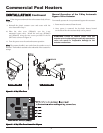
Outdoor Operation - Outdoor 3-Way
Automatic Bypass Valve Cover
The pump supplied on the pool heater bypass has a sealed motor
suitable for outdoor installations. When installing the 3-way
automatic bypass valve outdoors, an outdoor valve cover is required.
An outdoor valve cover is supplied with an optional outdoor vent
kit (see Table H, page 26 of this manual).
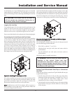
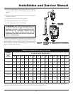
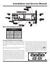
To install the outdoor valve cover, follow the steps below:
1. Turn off power to the unit.
2. Remove the plastic actuator cover from the 3-way
automatic bypass valve by loosening the screw above the
conduit fitting (Figure 32).
3. Grasp the cover on the screw side and lift the cover up and
away from the valve.
4. Disconnect the wires at the terminal block (if connected).
5. Unscrew the plastic conduit cap from the conduit fitting
(Figure 32) and pull the plastic conduit hose and wires
from the valve.
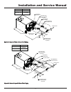
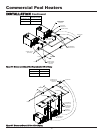
6. Feed the plastic conduit hose through the opening of the
valve cover end cap (JKD6654) (see Figure. 32) and slide
the end cap approximately one foot up the conduit.
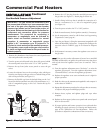
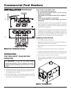
7. Reconnect the wires to the 3-way valve circuit board as
shown in Figure 33.
8. Feed the conduit hose into the conduit fitting and
reinstall the conduit cap.
31