


THX9321 PRESTIGE
®
2.0 AND THX9421 PRESTIGE
®
IAQ 2.0 WITH EIM
68-0311—01 50
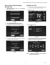
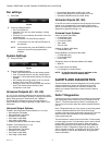
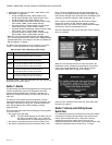
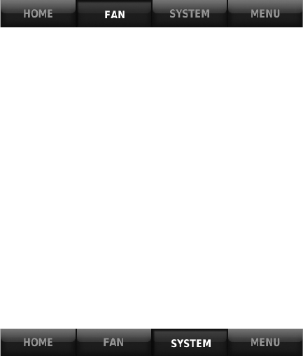
Fan settings
1. Press FAN.
Fig. 50.
2. Press any displayed option:
• On: Fan is always on.
• Automatic: Fan runs only when heating or cooling
system is on.
• Circulate: Fan runs randomly, about 35% of the time
(residential only).
• Follow Schedule: Fan controlled by program.
NOTE: In commercial use, the CIRCULATE option is
not available.
NOTE: In commercial use, press AUTOMATIC or ON to
temporarily override the programmed fan
schedule.
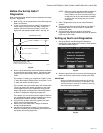
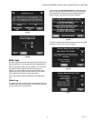
System Settings
1. Press SYSTEM.
Fig. 51.
2. Press any displayed option
• Heat: Thermostat controls only the heating system.
• Cool: Thermostat controls only the cooling system.
• Automatic: Thermostat selects heating or cooling as
needed.
• Off: Heating and cooling system is off. Fan will still
operate if fan is set to On or Circulate.
• Emergency Heat (only for heat pumps with auxiliary
heat): Thermostat controls Auxiliary Heat.
Compressor is not used.
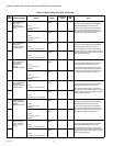
Universal Outputs (U1, U2, U3)
U1, U2, U3 are universal outputs that can be setup to control
IAQ equipment and a stage of heating or cooling in the Installer
Setup. Setup options are listed below. See “THX9321
Thermostat Wiring Diagrams Using Universal Relays to
Control Heating or Cooling” beginning on page 108 for more
information.
Universal Output Options
THX9421 with Equipment Interface Module (U1, U2, U3):
• Humidification (ISU 8030)
• Dehumidification (ISU 9040)
• Ventilation (ISU 10020)
• Cool Stage 3 (ISU 2080)
• Cool Stage 4 (ISU 2090)
• Geothermal Radiant Heat (ISU 2030, 2040)
THX9321 Thermostat Only (U1, U2)
• Humidification (ISU 8030)
• Dehumidification (ISU 9040)
• Ventilation (ISU 10020)
• Cool Stage 3 (ISU 2080)
• Cool Stage 4 (ISU 2090)
• Conventional Heat Stage 3 (ISU 2100, 2140)
• Backup Heat Stage 2 for Heat Pumps (ISU 2170)
• Geothermal Radiant Heat (ISU 2030, 2040)
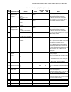
Universal Inputs (S1, S2)
S1 and S2 are universal inputs that can be setup to work with a
sensor or dry contact device in the Installer Setup. Setup
options and compatible sensors are listed below. See wiring
diagrams on page 58 and page 119.
Universal Input Options
Indoor Air Sensor (ISU 5000)
• C7189U1005 (10K)
• C7772A1004 (20K)
• C7772A1012 (20K)
• TR21 (20K)
• TR21-A (10K)
Outdoor Air Sensor (ISU 5000)
• C7089U1006 (10K)
Discharge/Return Air Sensors (ISU 5000)
• C7735A1000 (10k)
• C7770A1006 (20K)
• C7041 (20K)
Occupancy Sensor for Remote Setback (ISU 6000)
• WSK-24
Dry Contact Alerts (ISU 6000)
• Low Voltage Dry Contact Device
NOTE: S1 and S2 terminals are only available on the
Equipment Interface Module (EIM).
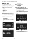
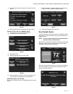
ALERTS AND DIAGNOSTICS
The thermostat uses alerts and diagnostics to provide greater
comfort and efficiency. Alerts and diagnostics can notify
customers when maintenance or service is needed, and
display your contact information to make it easy for them to
reach you.
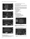
Delta T Diagnostics
If discharge and return air sensors are installed, the thermostat
can track system performance over time. It measures this as
“Delta T.” The thermostat monitors Delta T and displays an
alert on the home screen when the system exceeds the limits
you set.
Delta T Diagnostics tells you if the system is performing above
or below expected standards which would normally go
unnoticed, and may cause unnecessary energy use. It can also
detect and warn about problems early, before heating or
cooling equipment fails.
The thermostat will measure and record Delta T of the system
for each stage you test. This information can be used to set the
proper Delta T fault limits of the system. When the system
operates outside those limits multiple times (see “Advanced
Options for Delta T Diagnostics” beginning on page 53), an
alert is recorded in the log. If configured to do so, the system
will then display an alert to the homeowner, along with your
contact information.