


THX9321 PRESTIGE
®
2.0 AND THX9421 PRESTIGE
®
IAQ 2.0 WITH EIM
68-0311—01 108
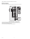
THX9321 Thermostat Wiring Diagrams
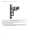
Using Universal Relays to Control Heating or Cooling
The THX9321 Thermostat and the EIM have universal outputs that can be configured for the following stages of heating and
cooling, based on the terminals available.
THX9321 THERMOSTAT (U1 AND U2)
• Cool Stage 3 (ISU 2080 - commercial only)
• Cool Stage 4 (ISU 2090 - commercial only)
• Conventional Heat Stage 3 (ISU 2100, 2140)
• Backup Heat Stage 2 for Heat Pumps (ISU 2170)
• Geothermal Radiant Heat (see wiring diagrams on
page 106, page 107, and page 110)
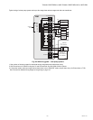
FOR THX9421 WITH EIM (U1, U2, AND U3)
• Cool Stage 3 (ISU 2080 - commercial only)
• Cool Stage 4 (ISU 2090 - commercial only)
• Geothermal Radiant Heat (see wiring diagrams on
page 106, page 107, and page 110)
NOTE: The EIM has dedicated terminals for
Conventional Heat Stage 3 and
Backup Heat Stage 2 for Heat Pumps
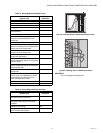
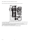
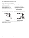
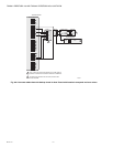
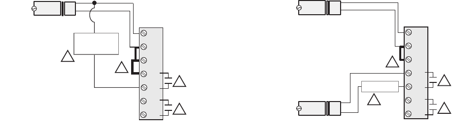
Powering universal relay with system transformer (THX9321
shown).
Fig. 215. Prestige THX9321 powering universal relay with
system transformer.
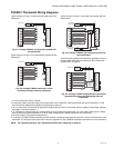
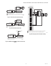
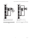
Powering universal relay with separate heating transformer
(THX9321 shown).
Fig. 216. Prestige THX9321 powering universal relay with
separate heating transformer.
1 U1/U2/U3 terminals are normally open dry contacts when set up for a stage of heating or cooling.
2 You must install a field jumper if the stage of heating or cooling is powered by system transformer. Do NOT install a field jumper
if the stage of heating has its own transformer.
3 U1/U2/U3 terminals are assigned to a stage of heating or cooling in the Installer Setup.
HEAT STAGE 3 or
COOL STAGE 3 or
COOL STAGE 4
120
VAC
C
Rc
R
U1
U1
U2
U2
24
VAC
Transformer
Thermostat
C
R
1
1
2
3
M32952
A
HEAT STAGE 3
120
VAC
C
Rc
R
U1
U1
U2
U2
24
VAC
Transformer
120
VAC
24
VAC
Transformer
Thermostat
C
R
C
R
1
1
2
3
M32953