


THX9321 PRESTIGE
®
2.0 AND THX9421 PRESTIGE
®
IAQ 2.0 WITH EIM
107 68-0311—01
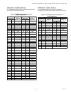
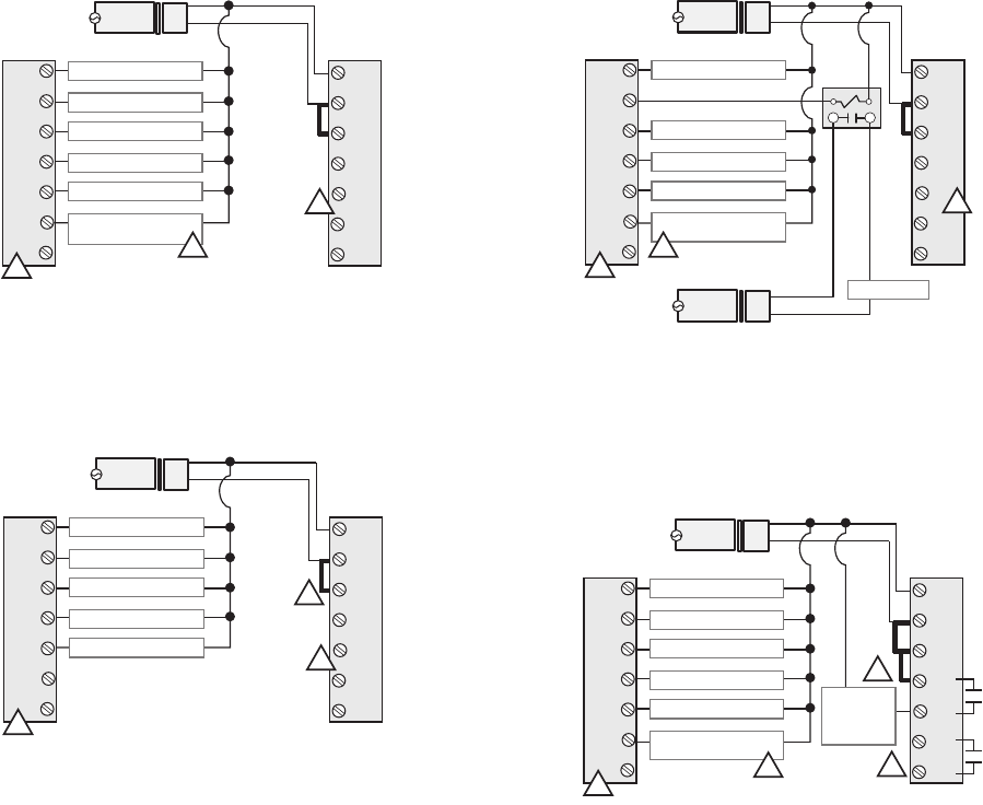
THX9321 Thermostat Wiring Diagrams
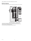
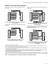
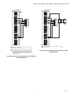
Typical wiring of a 3-heat / 2-cool heat pump system with one
transformer.
Fig. 211. Prestige THX9321 and heat pump system with
one transformer.
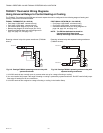
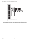
Typical wiring of a 2-heat / 2-cool conventional system with one
transformer.
Fig. 212. Prestige THX9321 and 2-heat / 2-cool
conventional system with one transformer.
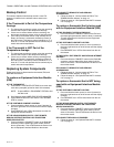
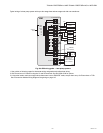
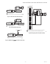
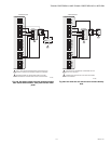
Typical wiring of a 3-heat / 2-cool heat pump system with two
transformers.
Fig. 213. Prestige THX9321 and heat pump system with
two transformers.
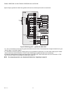
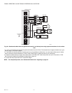
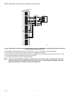
Typical wiring for geothermal radiant heat, geothermal forced-
air and backup heat with one transformer. See “Geothermal
Radiant Heat” on page 62.
Fig. 214. Prestige THX9321 and geothermal radiant heat,
geothermal forced-air and backup heat with one
transformer.
1 U1 and U2 terminals are dry contacts.
2 L/A terminal sends continuous output when thermostat is set to EM HEAT mode except when set up for Economizer or TOD.
See “Economizer Module Wiring Diagrams” beginning on page 116.
3 U1 or U2 terminals must be used for geothermal radiant heat (ISU 2010). Thermostat allows 2 stages of radiant heat—geother-
mal (stage 1) and boiler (stage 2).
4 “U” terminals are normally open dry contacts when set up for geothermal radiant heat. You must install a field jumper if radiant
heat is powered by system transformer. Do NOT install a field jumper if radiant heat has its own transformer.
5 Remove jumper if using separate transformers.
6 Connect the THP9045 Wiresaver Module to the K terminal in heating/cooling applications that do not have a common wire at the
thermostat. The K terminal cannot be used in heat-only applications. See THP9045 installation instructions for more information.
NOTE: For setup and operation, see “Geothermal Radiant Heat” beginning on page 62.
CHANGEOVER VALVE
BACKUP HEAT
COMPRESSOR STAGE 1
COMPRESSOR STAGE 2
FAN RELAY
COMPRESSOR MONITOR
OR ZONE PANEL
120
VAC
O/B
AUX/E
Y
Y2
G
L/A
K
C
Rc
R
U1
U1
U2
U2
24
VAC
Transformer
Thermostat
C
R
1
2
6
M32948A
HEAT STAGE 1
HEAT STAGE 2
COMPRESSOR STAGE 1
COMPRESSOR STAGE 2
FAN RELAY
120
VAC
W
W2
Y
Y2
G
A
K
C
Rc
R
U1
U1
U2
U2
24
VAC
Transformer
Thermostat
C
R
1
5
6
M32949A
31
CHANGEOVER VALVE
COMPRESSOR STAGE 1
COMPRESSOR STAGE 2
FAN RELAY
COMPRESSOR MONITOR
OR ZONE PANEL
120
VAC
O/B
AUX/E
Y
Y2
G
L/A
K
C
Rc
R
U1
U1
U2
U2
24
VAC
Air Handler
Transformer
120
VAC
24
VAC
Backup Heat
Transformer
C
R
R
C
Thermostat
BACKUP HEAT
1
2
6
M32950A
CHANGEOVER VALVE
BACKUP HEAT
COMPRESSOR STAGE 1
COMPRESSOR STAGE 2
FAN RELAY
COMPRESSOR MONITOR
OR ZONE PANEL
120
VAC
O/B
AUX/E
Y
Y2
G
L/A
K
C
Rc
R
U1
U1
U2
U2
24
VAC
Transformer
Thermostat
C
R
GEOTHERMAL
RADIANT
HEAT
STAGE 1
3
2
4
6
M32951A