


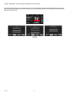
THX9321 PRESTIGE
®
2.0 AND THX9421 PRESTIGE
®
IAQ 2.0 WITH EIM
68-0311—01 102
WIRING
* Equipment Interface Module only
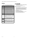
CAUTION
Electrical Hazard.
Can cause electrical shock or equipment damage.
Disconnect power before wiring.
All wiring must comply with local electrical codes and
ordinances. See Fig. 208–216.
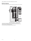
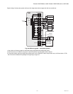
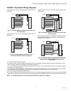
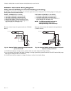
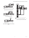
1. Select wiring diagram that corresponds with system type
and the equipment being installed (using the EIM or wir-
ing the thermostat directly to the HVAC equipment).
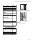
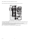
2. Loosen the screws for the appropriate terminals. Insert
wires in the terminal block under the loosened screw.
See Fig. 206.
3. Securely tighten each screw.
4. Push excess wire back into the hole.
5. Plug the hole with nonflammable insulation to prevent
drafts from affecting the thermostat.
6. See Fig. 208–216 for typical wiring hookups.
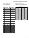
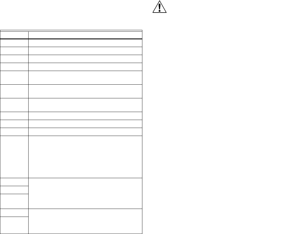
Table 11. Terminal Designation Descriptions.
Terminals Function
C 24 VAC Transformer Common
R 24 VAC Transformer Power
Rc 24 VAC Cooling Transformer Power
Rh 24 VAC Heating Transformer Power
W-O/B Heat Relay Stage 1 (Conventional Systems)
Changeover Valve (Heat Pump Systems)
W2-AUX 1 Heat Relay Stage 2 (Conventional Systems)
Auxiliary Heat Stage 1 (Heat Pump Systems)
W3-AUX 2* Heat Relay Stage 3 (Conventional Systems)
Auxiliary Heat Stage 2 (Heat Pump Systems)
Y Compressor Stage 1
Y2 Compressor Stage 2
GFan
A-L/A • Economizer or TOD output (commercial)
• Heat Pump Compressor Monitor - Thermostat
displays an alert when this terminal receives
24 volts.
• Sends continuous output when set to EM
HEAT except when setup for Economizer or
TOD. Connect terminal to zone panel.
U1, U1 Control humidification, dehumidification,
ventilation or a stage of heat/cool. The U1, U2,
U3 terminals are dry contacts that require power
from the system transformer or a separate
transformer.
U2, U2
U3, U3*
S1, S1* Connect to Indoor, Outdoor, Discharge or Return
Air Sensor, Occupancy Sensor for Remote
Setback or a Dry Contact Device to display an
alert.
S2, S2*