


5
C07075
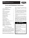
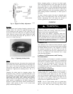
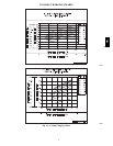
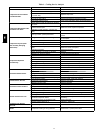
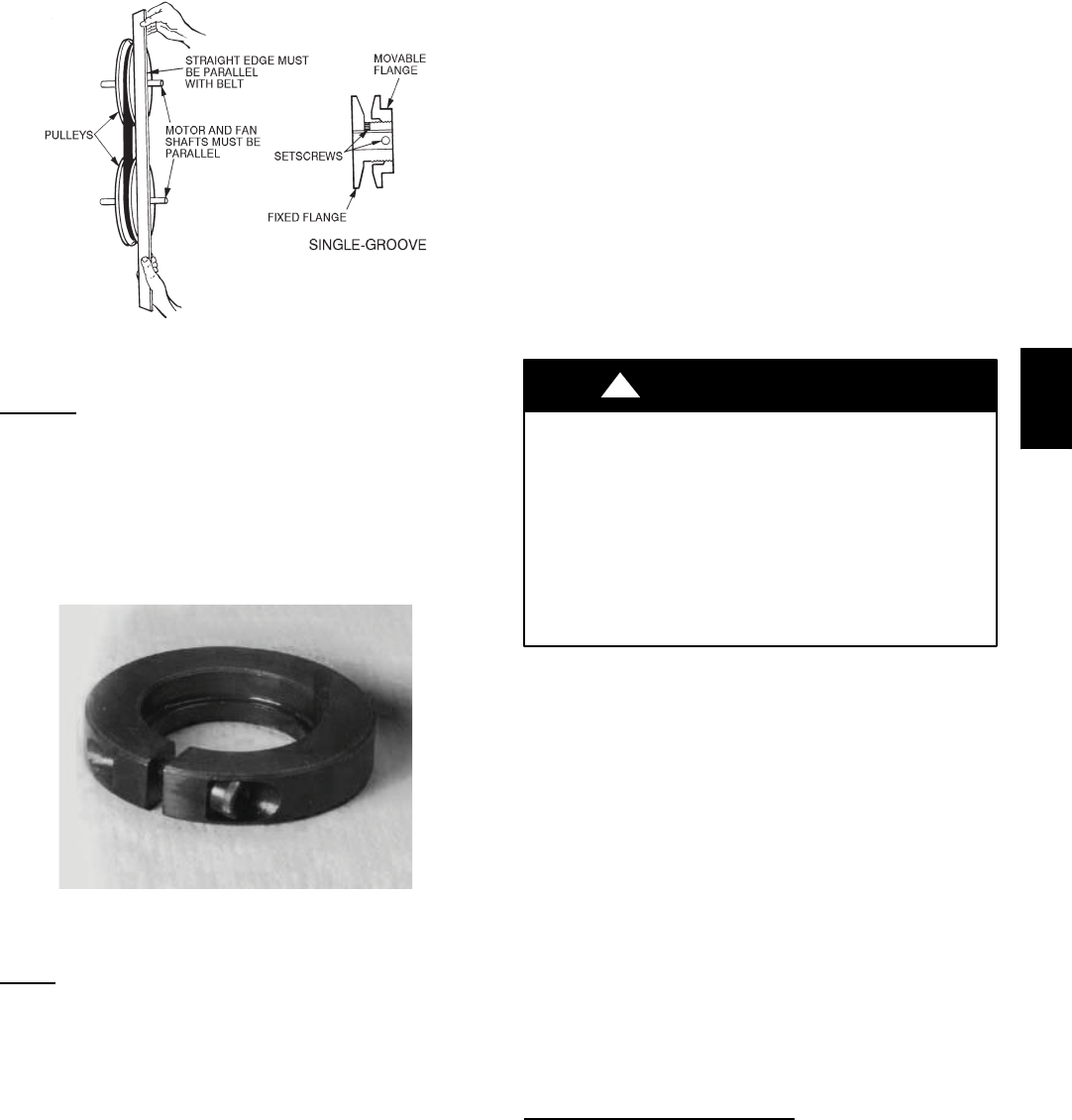
Fig. 6 -- Supply--Fan Pulley Adjustment
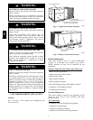
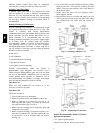
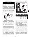
Beari ngs
This fan system uses bearings featuring concentric split
locking collars. The collars are tightened through a cap
screw bridging the split portion of the collar. The cap
screw has a Torx T25 socket head. To tighten the locking
collar: Hold the locking collar tightly against the inner
race of the bearing and torque the cap screw to 65--70
in--lb (7.4-- 7.9 Nm). See Fig. 7.
C08121
Fig. 7 -- Tightening Locking Collar
Motor
When replacing the motor, also replace the e xternal--tooth
lock washer (star washer) under the motor mounti ng base;
this is part of the motor grounding system. Ensure the
teeth on the lock washer are in contact with the motor’s
painted base. Tighten motor mounting bolts to 120 +/-- 12
in--lbs.
Changing fa n wheel speed by changing pulle ys: The
horsepower rating of the belt is primarily dictated by the
pitch diameter of the smaller pulley in the drive system
(typically the motor pulley in these units). Do not install a
replacement motor pulley with a smaller pitch diameter
than provided on the original factory pulley. Change fan
wheel speed by changing the fan pulley (larger pitch
diameter to reduce wheel speed, smaller pitch diameter to
increase wheel speed) or select a new system (both
pulleys and matching belt(s)).
Before changing pulleys to increase fan wheel speed,
check the fan performance at the target speed and airflow
rate to determine new motor loading (bhp). Use the fan
performance tables or use the Packaged Rooftop Builder
software program. Confirm that the motor in this unit is
capa ble of operating at the new operating conditi on. Fan
shaft loading increases dramatically as wheel speed is
increased.
To reduce vibration, replace the motor’s adjustable pitch
pulley with a fixed pitch pulley (after the final airflow
bala nce adjustment). This will reduce the amount of
vibration generated by the motor/belt--drive system.
COOLING
UNIT OPERATION AND SAFETY HAZARD
Failure to foll ow this warning could cause personal
injury, death and/or equipment damage.
This system uses PuronR refrigerant which has
higher pressures than R--22 and other refrigerant s. No
other refrigerant may be used in this system. Gauge
set, hoses, and recovery system must be designed to
handle Puron refrigerant. If unsure about equipment,
consult the equipment manufacturer.
!
WARNING
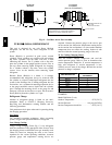
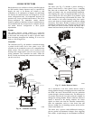
Condenser Coil
The condenser coil is fabricated with round tube copper
hairpins and plate fins of various material s and/or coatings
(see Model Number Format in the Appendix to identify
the materials provided in this unit). The coil may be
one--row or composite--type two--row. Composite two--row
coils are two single--row coils fabricated with a single
return bend end tubesheet.
Condenser Coil Maintenance and Cleaning
Recommendation
Routine cleaning of coil surfaces is essential to maintain
proper operation of the unit. Elimination of contamination
and removal of harmful residues will greatly increase the
life of the coil and extend the life of the unit. The
following maintenance and cleaning procedures are
recommended as part of the routine maintenance activities
to extend the life of the coil.
Remove Surface Loaded
Fibers
Surface loaded fibers or dirt should be removed with a
vacuum cleaner. If a vacuum cleaner is not available, a
soft non--metallic bristle brush may be used. In either
case, the tool should be applied in the direction of the fins.
Coil surfaces can be easily damaged (fin edges can be
easily bent over and damage to the coating of a protected
coil) if the tool is applied across the fins.
NOTE: Use of a water stream, such as a garden hose,
against a surface loaded coil will drive the fibers and dirt
into the coil. This will make cleaning efforts more
580J