


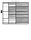

37
SUPPLY AIR
TEMPERATURE
SENSOR
MOUNTING
LOCATION
SUPPLY AIR
TEMPERATURE
SENSOR
C06033
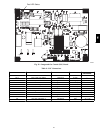
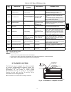
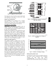
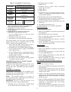
Fig. 44 -- Supply Air Sensor Location
The temperature sensor looks like an eye let terminal with
wires running to it. The sensor is locate d in the “crimp
end” and is sealed from moisture.
Outdoor Air Lockout Sensor
The E conoMi$er IV is equipped with an ambient
temperature lockout switch located in the outdoor
airstream which is used to lock out the compressors below
a42_F(6_C) ambient temperature. (See Fig. 38.)
EconoMi$e r IV Control
Modes
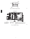
IMPORTANT : The optional EconoMi$er2 does not
include a controller. The EconoMi$er2 is operated by a 4
to 20 mA signal from an existing field-supplied controller.
See Fig. 42 for wiring information.
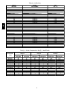
Determine the EconoMi$er IV control mode before set up
of the control. Some modes of operation may require
different sensors. (See Table 17.) The EconoMi$er IV is
supplied from the fact ory with a supply--air temperature
sensor and an outdoor--air temperature sensor. This allows
for operation of the EconoMi$er IV with outdoor air dry
bulb changeover control. Additional accessories can be
added to allow for different types of changeover control
and operation of the EconoMi$er IV and unit.
Outdoor Dry Bulb Changeover
The standard controller is shipped from the factory
configure d for outdoor dry bul b changeover control. The
outdoor air and supply air temperature sensors are
included as standard. For this control mode, the outdoor
temperature is compared to an adjustable setpoint selected
on the control. If the outdoor-air temperature is above the
setpoint, the EconoMi$er IV will adjust the outside air
dampers to minimum position. If the outdoor-air
temperature is below the setpoint, the position of the
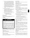
outside air dampers will be controlle d to provided free
cooling using outdoor air. W hen in this mode, the LED
next to the free cooling setpoint potentiometer will be on.
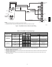
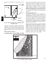
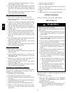
The changeover temperature setpoint is controlled by the
free cooling setpoint potentiometer located on the control.
(See Fig. 45.) The scale on the potentiometer is A, B, C,
and D. See Fig. 46 for the corresponding temperature
change over values.
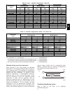
C06034
Fig. 45 -- EconoMi$er IV Controller P otentiometer
and LED Locations
LED ON
LED ON
LED ON
LED ON
LED OFF
19
18
LED OFF
LED OFF
LED OFF
17
16
15
14
13
12
11
10
9
40
45
50
55
60
65
70
75
80
85
90
95
100
DEGREES FAHRENHEIT
mA
D
C
B
A
C06035
Fig. 46 -- Outside Air Temperature Changeover
Setpoints
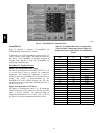
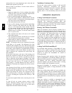
0
5
10
15
20
25
30
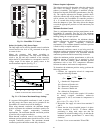
0.13 0.20 0.22 0.25 0.30 0.35 0.40 0.45 0.50
STATIC PRESSURE (in. wg)
FLOW IN CUBIC FEET PER MINUTE (cfm)
C06031
Fig. 47 -- Outdoor--Air Damper Leakage
Differential Dry Bulb Control
For differential dry bulb control the standard outdoor dry
bulb se nsor is used in conjunction with an additional
accessory dry bulb sensor (part number
CRTEMPSN002A00). The accessory sensor must be
mounted in the return airstream. (See Fig. 48.) Wiring is
580J