


16
SMOKE DETECTORS
Smoke detectors are ava ilable as factory--installed options
on 580J models. Smoke detectors may be speci fied for
Supply Air only or for Return Air without or with
econom izer or in combinati on of Supply Air and Return
Air. Return Air smoke detectors are arranged for vertical
return configurations only. All components necessary for
operation are factory--provided and mounted. The unit is
factory--configured for immediate smoke detector
shutdown operation; additional wiring or modifications to
unit terminal board may be necessary to complete the unit
and smoke detector configuration to meet project
requirements.
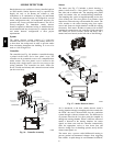
System
The smoke detector system consists of a four--wire
controller and one or two sensors. Its primary function is
to shut down the rooftop unit in order to prevent smoke
from circulating throughout the building. It is not to be
used as a life saving device.
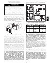
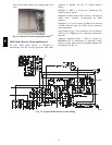
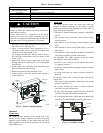
Controller
The controller (see Fig. 16) i ncludes a controller housing,
a printed circuit board, and a clear plastic cover. The
controller can be connected to one or two compatible duct
smoke sensors. The clear plastic cover is secured to the
housing with a single captive screw for easy access to the
wiring terminals. The controller has three LEDs (for
Power, Trouble and Alarm) and a manual test/reset button
(on the cover face).
Duct smoke sensor
controller
Fastener
(2X)
Controller cover
Conduit nuts
(supplied by installer)
Conduit support plate
Cover gasket
(ordering option)
Conduit couplings
(supplied by installer)
Terminal block cover
Controller housing
and electronics
Alarm
Power
Te s t / r e s e t
switch
Trouble
C08208
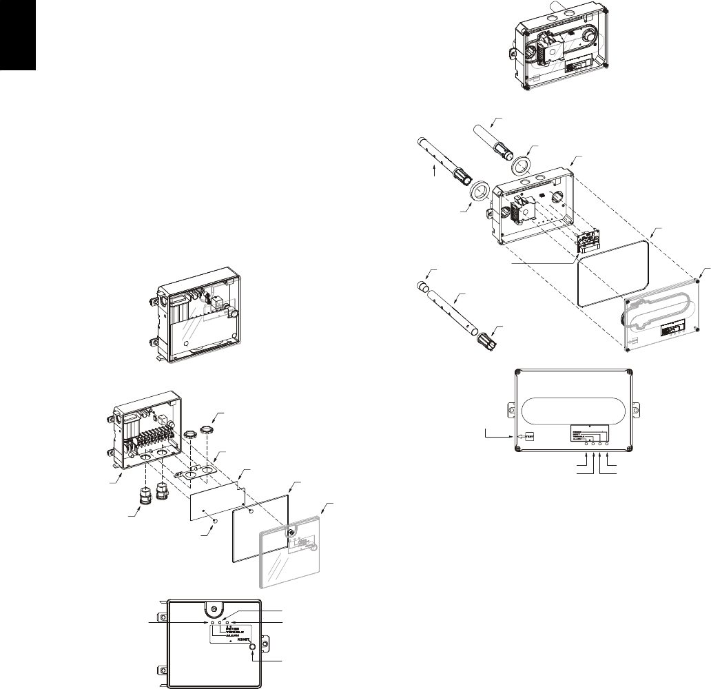
Fig. 16 -- Controller Assembly
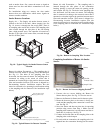
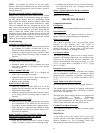
Sensor
The sensor (see Fig. 17) includes a pl astic housing, a
printed circuit board, a clear plastic cover, a sampling
tube inlet and an exhaust tube. The sampling tube (when
used) and exhaust tube are attached during instal lation.
The sampling tube varies in length depending on the size
of the rooftop unit. The clear plastic cover permits visual
inspections without having to disassemble the sensor. The
cover attaches to the sensor housing using four captive
screws and forms an airtight chamber around the sensing
electronics. Each sensor includes a harness with an RJ45
terminal for connecting to the controll er. Each sensor has
four LEDs (for Power, Trouble, Alarm and Dirty) and a
manua l test/reset button (on the left--side of the housing).
Duct smoke sensor
See
Detail A
Exhaust tube
Plug
Sampling tube
(ordered separately)
Intake
gasket
Cover gasket
(ordering option)
TSD-CO2
(ordering option)
Sensor housing
and electronics
Exhaust gasket
Coupling
Sensor cover
Detail A
Magnetic
test/reset
switch
Alarm
Trouble
Power
Dirty
C08209
Fig. 17 -- Smoke Detector Sensor
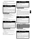
Air i s introduced to the duct smoke detector sensor’s
sensing chamber through a sampling tube that extends int o
the HVAC duct and is directed back into the ventilation
system through a (shorter) exhaust tube. The difference in
air pressure between the two tubes pulls the sampled air
through the sensing chamber. When a sufficient amount of
smoke is detected in the sensing chamber, the sensor
signals an alarm state and the controller automatically
take s the appropriate action to shut down fans and
blowers, change over air handling systems, notify the fire
alarm control panel, etc.
The sensor uses a process called differential sensing to
prevent gra dual environmental changes from triggering
false alarms. A ra pid change in environm ental conditions,
580J