


17
such as smoke from a fire, causes t he sensor to signal an
alarm state but dust and debris accumulated over time
does not.
For installations using two sensors, the duct smoke
dete ctor doe s not di fferentiate which sensor signals an
alarm or trouble condition.
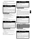
Smoke Detector Locations
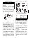
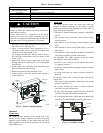
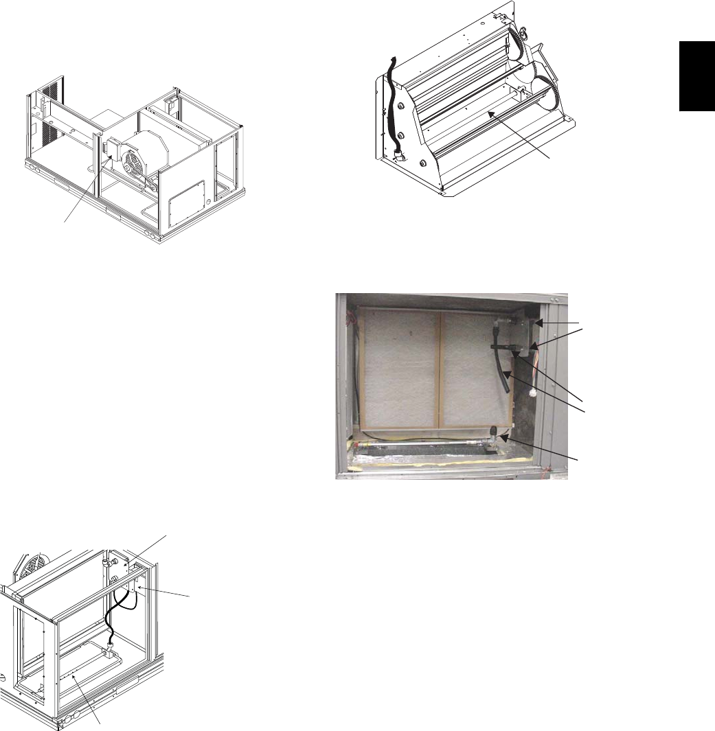
Supply Air — The Supply Air smoke detector sensor is
located to the left of the unit’s indoor (supply) fan. See
Fig. 18. Access is through the fan access panel. There is
no sampling tube used at this location. The sampling tube
inlet extends through the side plate of the fan housing
(into a high pressure area). The controller is located on a
bracket to the right of the return filter, accessed through
the lift-- off filter panel.
Smoke Detector Sensor
C08245
Fig. 18 -- Typical Supply Air Smoke Detector Sensor
Location
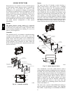
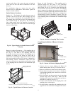
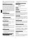
Return Air without Economizer — The sampling tube is
located across the return air opening on the unit basepan.
See Fig. 19. The holes in the sampling tube face
downward, into the return air stream. The sampling tube is
connec ted via tubing to the return air sensor that is
mounted on a bracket high on the partition between return
filter and controller location. (This sensor is shipped in a
flat--mounting locati on. Installation requires that this
sensor be relocated t o its operating location and the tubing
to the sampling tube be connected. See installation steps
below.)
Return Air Detector Sampling Tube
Controller module
Return Air Detector module
(shipping position shown)*
*RA detector must be moved from shipping position to operating position by installer
C07307
Fig. 19 -- Typical Return Air Detector Location
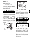
Return Air with Economizer — The sampling tube is
inserted through the side plates of the economize r
housing, placing it across the return air opening on the
unit basepan. See Fig. 20. The holes in the sampl ing tube
face downward, into the return air stream. The sampling
tube is connec ted via tubing to the return air sensor that is
mounted on a bracket high on the partition between return
filter and controller location. (This sensor is shipped in a
flat--mounting locati on. Installation requires that this
sensor be relocated t o its operating location and the tubing
to the sampling tube be connected. See installation steps
below.)
Return Air
Sampling Tube
C08129
Fig. 20 -- Return Air Sampling Tube Location
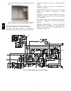
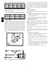
Completing Installation of Return Air Smoke
Sensor:
Flexible
Exhaust Tubes
Screws
Sample Tube
C08126
Fig. 21 -- Return Air Detector Shipping Position
1. Unscrew the two screws holding t he Return Air
Sensor detect or plate. See Fig. 21. Save the screws.
2. Remove the Return Air Sensor and its detector pla te.
3. Rotate the detector plate so the sensor is facing out-
wards and the sampling tube connection is on the bot-
tom. See Fig. 22.
4. Screw the sensor and de tector plate into its operating
position using screws from Step 1. Make sure the
sampling tube connection is on the bottom and the ex-
haust tube is on the top. See Fig. 22.
5. Connect the flexible tube on the sampling inlet to the
sampling tube on the basepan.
6. For units with an economizer, the sampling tube is in-
tegra ted into the economizer housing but the connec-
580J