


25
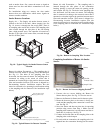
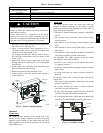
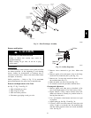
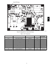
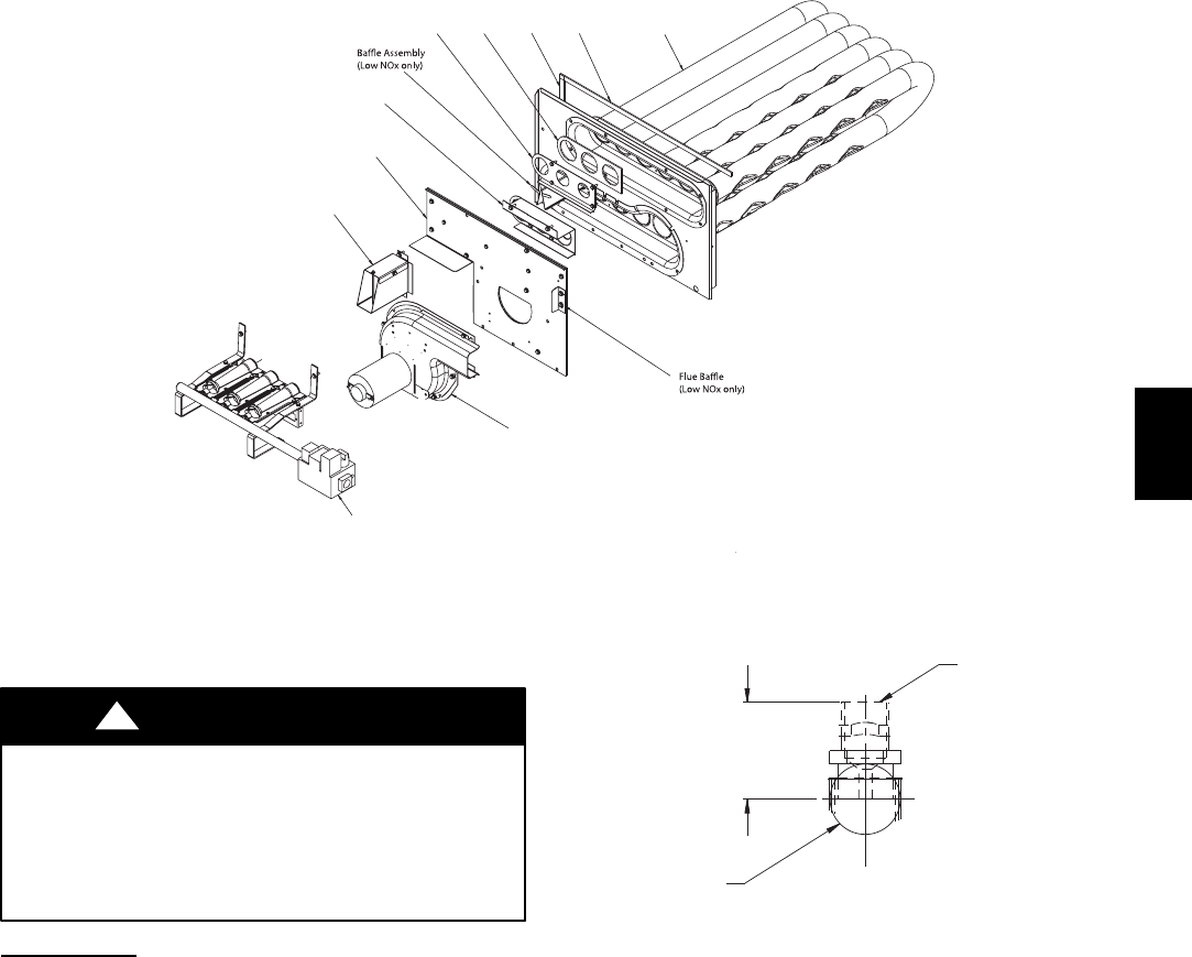
Heater Tube
Assembly
Seal Strips, Sponge Rubber
Regulator
Gasket
Regulator
Retainer
Support
Insulation
Assembly
Wind Cap Assembly
(shown inverted,
as shipped)
Burner Assembly
Inducer Fan-Motor
Assembly
C08227
Fig. 31 -- Heat Exchanger Assembly
Burners and Igniters
EQUIPMENT DAMAGE HAZARD
Failure to follow this caution may result in
equipment damage.
When working on gas train, do not hit or plug
orifice spuds.
CAUTION
!
Main Burners
To access burners, remove burner access panel and slide
out burner partition. At the beginning of each heating
season, inspect for deterioration or blockage due to
corrosion or other causes. Observe the main burner flames
and adjust, if necessary.
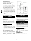
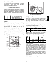
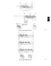
Orifice projection — Refer to Fig. 32 for maximum
projection dimension for orifice face to manifold tube.
Removal and Replacement of Gas Train
See Fig. 27, Fig. 31 and Fig. 33.
1. Shut off manual gas valve.
2. Shut off power to unit.
3. Slide out burner partition.
4. Disconnect gas piping at unit gas valve.
Orifice
1.00-in
(25.4 mm)
Manifold
Pipe
C08211
Fig. 32 -- Orifice Projection
5. Remove wires connected to gas valve. Mark each
wire.
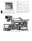
6. Remove igniter wires and sensor wires at the Integ-
rated Gas Unit Controller (IGC). (See Fig. 34.)
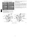
7. Remove the 2 screws that attach the burner rack to
the vestibule plate (Fig. 27).
8. Slide the burner tray out of the unit (Fig. 33).
9. To reinstall, reverse the procedure outlined above.
Cleaning and Adjustment
1. Remove burner rack from unit as described in Re-
moval and Replacement of Gas Train section, above.
2. Inspect burners; if dirty, remove burners from rack.
(Mark each burner to identify its position before re-
moving from the rack.)
3. Use a soft brush to clean burners and cross--over port
as required.
4. Adjust spark gap. See Fig. 35 and Fig. 36.
5. If factory orifice has been removed, check that each
orifice is tight at its threads into the manifold pipe
and that orifice projection does not exceed maximum
valve. See Fig. 32
580J