


42
when the potentiometer is approximately 9--v. The ac-
tuator should drive fully closed.
6. Turn the DCV and Exhaust pot entiomet ers CCW unti l
the Exhaust LED turns on. The exhaust contacts wil l
close 30 to 120 seconds after the Exhaust LED turns
on.
7. Return EconoMi$er IV settings and wiring to normal
afte r completing troubleshooting.
DCV Minimum and Maximum
Position
To check the DCV minimum and maximum position:
1. Make sure EconoMi$er IV preparation proc edure has
been performed.
2. Connect a 9--v battery to AQ (positive node) and AQ1
(negat ive node). The DCV LED should turn on. The
act uator should drive to between 90 and 95% open.
3. Turn the DCV Maximum Position potentiometer to
midpoint. The actuator should drive to between 20
and 80% open.
4. Turn the DCV Maximum Position potentiometer to
fully CCW. The actuator should drive fully closed.
5. Turn the Minimum Position potentiometer to mid-
point. The actuator should drive to between 20 and
80% open.
6. Turn the Minimum Position Potentiometer fully CW.
The ac tuator should drive fully open.
7. Remove the jum per from TR and N. The actuator
should drive fully closed.
8. Return EconoMi$er IV settings and wiring to normal
afte r completing troubleshooting.
Supply--Air Sensor
Input
To check supply--air sensor input:
1. Make sure EconoMi$er IV preparation proc edure has
been performed.
2. Set the Enthalpy potentiometer to A. The Free Cool
LED turns on. The actuator should drive to between
20 and 80% open.
3. Remove the 5.6 kilo--ohm resistor and j umper T to
T1. The actuator should drive fully open.
4. Remove the jumper across T and T1. The actuator
should drive fully closed.
5. Return EconoMi$er IV settings and wiring to normal
afte r completing troubleshooting.
EconoMi$e r IV Troubleshooting
Completion
This procedure is used to return the EconoMi$er IV to
operat ion. No troubleshooting or testing is done by
performing the following procedure.
1. Disconnect power at TR and TR1.
2. Set enthalpy potentiometer to previous setting.
3. Set DCV maximum position potentiometer to previ-
ous setting.
4. Set minimum position, DCV setpoint, and exhaust po-
tentiometers to previous settings.
5. Remove 620--ohm resistor from term inals SR and +.
6. Remove 1.2 kilo--ohm checkout resistor from termin-
als SO and +. If used, reconnect sensor from termin-
als SO and +.
7. Remove jumper from TR to N.
8. Remove jumper from TR to 1.
9. Remove 5.6 kilo--ohm resistor from T and T1. Recon-
nect wires at T and T1.
10. Remove jumper from P to P1. Reconnect device at P
and P1.
11. Apply power (24 vac) to terminals TR and TR1.
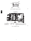
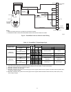
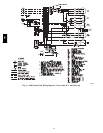
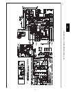
WIRING DIAGRAMS
See Fig. 52 and Fig. 53 for typical wiring diagrams.
PRE-- START--UP
PERSONAL INJURY HAZARD
Failure to foll ow this warning could result in personal
injury or death.
1. Follow recognized safety practices and wear pro-
tective goggles when checking or servicing re fri-
gerant system.
2. Do not operate compressor or provide any electric
power to unit unless compressor terminal cover is
in place and secured.
3. Do not remove compressor terminal cover until
all electrical sources are disconnected.
4. Relieve all pressure from system be f ore touching
or disturbing anything inside terminal box if refri-
gerant lea k is suspected around compressor ter-
minals.
5. Never a ttempt to repa ir soldered connection while
refrigerant system is under pressure.
6. Do not use torch to re move any component. Sys-
tem conta ins oil and refrigerant under pressure.
To remove a component, wear protective goggles
and proceed as follows:
a. Shut off electrical power and then gas to unit.
b. Recover refrigerant to relieve all pressure from
system using both high--pressure and low
pressure ports.
c. Cut component connection tubing with tubing
cutter and remove component from unit.
d. Carefully unsweat remaining tubing stubs
when necessary. Oil can ignite when exposed
to torch flame.
!
WARNING
Proceed as follows to inspect and prepare the unit for
initial start--up:
1. Remove all access panels.
2. Read and follow instructions on all WARNING,
CAUTION, and INFORMATION labels attached to,
or shipped with, unit.
3. Make the following inspections:
a. Inspect for shipping and handling damages such
as broken lines, loose parts, or disconnected
wires, etc.
580J