


26
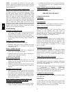
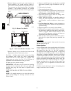
6. Reinstall burners on rack in the same locations as
factory--install ed. (The outside crossover flame re-
gions of the oute rmost burners are pinched off to pre-
vent excessive gas flow from the side of the burne r
assembly. If the pinched crossovers are instal led
betwee n two burners, the flame will not ignite prop-
erly.)
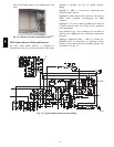
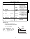
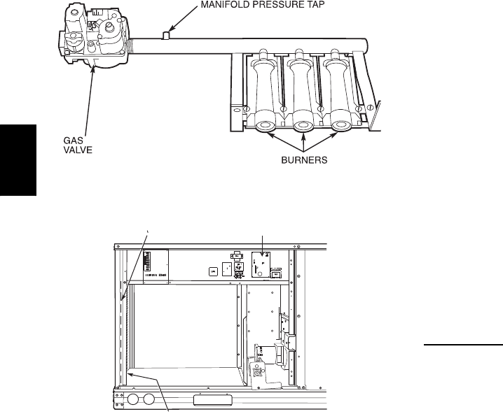
C06153
Fig. 33 -- Burner Tray Details
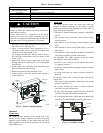
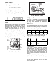
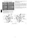
RACEWAY
INTEGRATED GAS UNIT
CONTROLLER (IGC)
HOLE IN END PANEL (HIDDEN)
C08454
Fig. 34 -- Unit Control Box/IGC Location
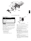
7. Reinstall burner rack as described in Removal and
Replacement of Gas Train section, above.
Gas Valve — All three --phase models (except Low NO
x
)
are equipped with 2--stage gas valves. Single--phase
models and all Low NO
x
models are equipped with
single--stage gas val ves. See Fig. 37 for locations of
adjustment screws and features on the gas valves.
To adjust gas valve pressure settings:
IMPORTANT : Leak check all gas connections including
the main service connection, gas valve, gas spuds, and
manifold pipe plug. All leaks must be repaired before
firing unit.
Check Unit Operation and Make Necessary Adjust-
ments
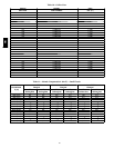
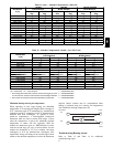
NOTE: Gas supply pressure at gas valve inlet must be
within specified ranges for fuel type and unit size. See
Tables 4 and 5.
1. Remove manifold pressure tap plug from manifold
and connect pressure gauge or manomete r. (See Fig.
33)
2. Turn on electrical supply.
3. Turn on unit main gas valve.
4. Set room thermostat to call for heat. If unit has two--
stage gas valve, verify high--stage heat operation be-
fore attempting to adjust manifold pressure.
5. When main burners ignite, check all fittings, mani-
fold, and orifices for leaks.
6. Adjust high--stage pressure to specified setting by
turning the plastic adjustment screw clockwise to in-
crea se pressure, counter--cl ockwise to decrease pres-
sure.
7. For Two--Stage Gas Valves set room thermostat to
call for low--stage heat. Adjust low--stage pressure to
specified setting.
8. Replace regulator cover screw(s) when finished.
9. With burner access panel removed, observe unit heat-
ing operation in both high stage and low stage opera-
tion if so equipped. Observe burner flames to see if
they are blue in appearance, and that the flames are
approximately the same for each burner.
10. Turn off unit , remove pressure manometer and re-
place the 1/8 in. pipe fitting on the gas manifold. See
Fig. 33.
Limit
Switch
Remove blower access panel. Limit switch is located on
the fan deck. See Fig. 28.
Burner Ignition
Unit is equipped with a direct spark i gnition 100% lockout
system. Integrated Gas Unit Controller (IGC) is located in
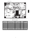
the control box. See Fig. 34. The IGC conta ins a
self--diagnostic LED (light--emitting diode). A single LED
(see Fig. 38) on the IGC provides a visual display of
operat ional or sequential problems when the power supply
is uninterrupted. When a break in power occurs, the IGC
will be reset (resulting in a loss of fault history) and the
indoor (evaporator) fan ON/OFF times will be reset. The
LED error code can be observed through the viewport.
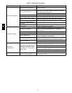
During servicing refer to the label on the control box
cover or Table 8 for an explanati on of LED error code
descriptions.
If lockout occurs, unit may be reset by interrupting power
supply to unit for at least 5 seconds.
580J