


44
setting below the room temperature and verify that the
burners and evaporator fa n turn off.
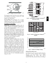
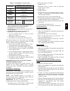
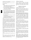
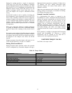
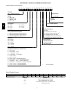
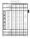
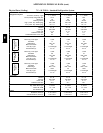
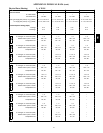
Refer to Table 11 and Table 12 for the correct orifice to
use at high altitudes.
Heating
1. Purge gas supply line of air by opening uni on ahead
of the gas valve. If gas odor is detected, t ighten union
and wait 5 minutes before proceeding.
2. Turn on electrical supply and manual gas valve.
3. Set system switch selector at HEAT position and fan
switch at AUTO. or ON position. Set heating temper-
ature lever above room tempe rature.
4. The induced--draft motor will start.
5. After a call for heating, the main burners should light
within 5 seconds. If the burner does not light , then
there is a 22--second delay before another 5--second
try. If the burner still does not light, the time delay is
repea ted. If the burner does not light within 15
minutes, there is a lockout. To reset the control, break
the 24 v power to W1.
6. The evaporator--fan motor will turn on 45 seconds
afte r burner ignition.
7. The evaporator--fan motor will turn off in 45 seconds
after the thermostat temperature is satisfied.
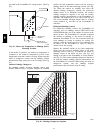
8. Adjust airflow to obtain a temperature rise within the
range specified on the unit nameplate.
NOTE: The default value for the evaporator--fan motor
on/off delay is 45 seconds. The Integrat ed Gas Unit
Controller (IGC) modifies this value when abnormal limit
switch cycles occur. Based upon unit operating conditions,
the on delay can be reduced to 0 seconds and the off delay
can be extended to 180 seconds. When one flash of the
LED is observed, the evaporator--fan on/off dela y ha s
been modified.
If the limit switch trips at the start of the heating cycle
during the evaporator on delay, the time period of the on
dela y for the next cycl e will be 5 seconds less than the
time at which the switch tripped. (Example: If the limit
switch trips at 30 seconds, the evaporator--fan on delay for
the next cycle will occur at 25 seconds.) To prevent
short--cycling, a 5 --second reducti on will only occ ur if a
minimum of 10 minutes has elapsed since the last ca ll for
heat ing.
The evaporator--fan off delay can also be modified. Once
the ca ll for heating has ended, there is a 10--minute period
during which the modification can occur. If the limit
switch trips during this period, the evaporator--fan off
dela y will increase by 15 seconds. A maximum of 9 trips
can occur, extending the evaporat or--fan off delay t o 180
seconds.
To restore the original default value, reset the power to the
unit.
To shut off unit, set system selector switch at OFF
position. Resetting heating selector lever below room
temperature will temporarily shut unit off until space
temperature falls below thermostat setting.
Ventilation (Continuous Fan)
Set fan and system selector switches at ON and OFF
positions, respective ly. Evaporator fan operates
continuously to provide constant air circulation. When the
evapora tor--fan selec tor switch is turned to the OFF
position, there is a 30--second delay before the fan turns
off.
OPERATING SEQUENCES
Cooling, Unit Without Economizer
When thermostat calls for cooling, terminals G and Y1 are
energized. The indoor--fan contactor (IFC) and
compressor contactor are e nergized and indoor--fan motor,
compressor, and outdoor fan start. The outdoor fanmotor
runs continuously while unit is cooling.
Heating, Unit Without Economizer
When the thermostat calls for heating, terminal W1 is
energized. To prevent thermostat short--cycling, the unit is
locked into the Heating mode for at least 1 minute when
W1 is energized. The induced-- draft motor is energized
and the burner ignition sequence begins. The indoor
(evapora tor) fan motor (IFM) is energized 45 seconds
afte r a flame is igni ted. On units equipped for two sta ges
of heat, when additional heat is needed, W2 is energized
and the high--fire solenoid on the main gas valve (MGV)
is energized. When the thermostat is satisfied and W1 is
deenergized, the IFM stops after a 45--second time-- off
dela y.
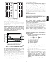
Cooling, Unit With EconoMi$er IV
For Occupied mode operation of EconoMi$e r IV, there
must be a 24--v signal at te rminals TR and N (provided
through PL6--3 from the unit’s IFC coil). Removing the
signal at N places the EconoMi$er IV control in
Unoccupie d mode.
During Occupie d mode ope ration, indoor fan operation
will be accompanied by economizer dampers moving to
Minimum Position setpoint for ventilation. If indoor fan is
off, dampers will close. During Unoccupied mode
operat ion, dampers will remain closed unless a Cooling
(by free cooling) or DCV demand is received.
Integrated EconoMi$er IV operation on 580J single
compressor model requires a 2--stage thermostat (Y1 and
Y2 switches).
When free cooling using outside air is not available, the
unit cooling sequence will be controlled directly by the
space thermostat as desc ribed above as Cooling, Without
Economizer. Outside air damper position will be closed or
Minimum Position as determined by occupancy mode and
fan signal.
When free cooling is available as determined by the
appropria te change over command (dry bul b, outdoor
enthalpy, differential dry bulb or differential enthalpy), a
call for cooling (Y1 closes at the thermostat) will cause
the ec onomizer control to modulate the dampers open and
closed to maintain the unit supply air temperature at 50 to
55_F. Compressor will not run.
580J